Matching and Solving Cameras
The next step after setting up the rig is to set the camera properties for the rig, locate matches between overlapping cameras, and solve the camera positions relative to each other.
| 1. | The Analysis section enables you to change the camera properties for the rig. By default, CaraVR assumes that all cameras have the same focal distance, no lens distortion, and a spherical layout. |
Set the Focal Length to account for:
• Known Focal Length - fixes the existing focal length in the solve.
• Optimize per Camera - calculates the focal length for each camera in the rig.
• Optimize Single - calculates a single optimized focal length for all cameras in the rig.
| 2. | Set the Lens Distortion, if required. CaraVR assumes No Lens Distortion by default, but like Focal Length, you can account for: |
• Known Distortion - fixes the lens distortion in the solve.
• Optimize per Camera - calculates the lens distortion for each camera in the rig.
• Optimize Single - calculates a single optimized lens distortion for all cameras in the rig.
| 3. | Set the Camera Layout you intend to use: |
• Nodal Layout - all cameras are located at the scene origin. For example, a single DSLR shooting 360 stills would use this nodal layout setting.
• Spherical Layout - the cameras in the rig are placed on a sphere whose diameter, defined by the Rig Size control on the Cameras tab, defaults to 30 cm.
• Horizontal / Vertical / Planar Layout - the cameras in the rig are placed on a single line or plane depending on selection.
• Free Layout - no constraints are enforced on camera positions.
Note: The Horizontal, Vertical, Planar, and Free layouts are experimental. Please contact support.foundry.com if you have any feedback you'd like to share with Foundry.
Tip: Setting the Rig Size control to the actual size of the rig in use allows you to enter real world measurements for other Cameras controls, such as Focal Length.
Rigs that utilize multiple cameras, filming concurrently, usually have a spherical configuration allowing you to alter the Convergence between cameras to check for image alignment at different depths in the scene. See Adjusting Convergence in Spherical Rigs for more information.
| 4. | CaraVR automatically adds a single keyframe at the beginning of the sequence to define a set of feature matches that correspond to fixed points in the scene, but you can add keyframes manually by: |
• scrubbing in the Viewer and then clicking Add Key (![]() ) to add a keyframe at the current frame, or
) to add a keyframe at the current frame, or
• clicking Key All to add keyframes throughout the sequence at the Step interval.
• clicking Import and selecting the node from which you want to import keyframes. You can import keyframes from any instance of C_CameraSolver, C_Stitcher, or C_ColourMatcher in the script.
The more keyframes you add, the longer the process takes, though you may get better results.
Note: C_Stitcher only computes optical flow camera warps at designated keyframes, it ignores upstream animation that does not fall on the same keyframes. Use the Import button to copy over all keyframes from C_CameraSolver. This way, any additional per-camera, manual keyframes added in the Cameras tab are also copied.
Tip: If you're solving a rig with a nodal layout, you can click the Settings tab and enable Solve for animated cameras to calculate animated values for the camera parameters at each of the analysis key frames.
This setting can help to eliminate ghosting in mono 360 nodal stitches by automatically adjusting the cameras to compensate for differing scene depths.
Bear in mind, however, that this setting may produce odd results if the camera position is fixed. Any changes in camera rotation at the analysis keys may cause the background scene to shift.
| 5. | Click Match to compare keyframes on overlapping cameras for shared features. CaraVR only looks for matches in cameras that overlap by default. |
Note: Match calculates the feature matches for all cameras in the rig at the same time, so there is no need to calculate them separately for left and right images in a stereo setup. See Stitching Stereographic Rigs for more information.
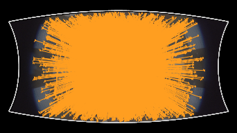
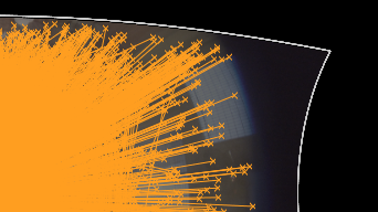
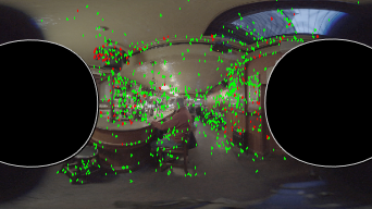
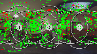
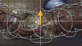
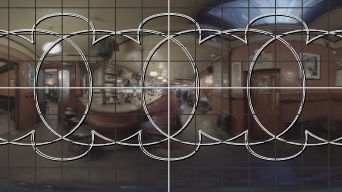
Initially, all the matched features for the cameras overlay each other in the Viewer. Individual matches won't be visible until you solve the cameras on the rig, or zoom into the Viewer as shown in the second image.
|
|
|
|
Feature matches for all cameras at different Viewer zoom levels. |
|
Note: Matches are only displayed when the playhead is on a keyframe.
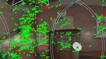
You can step through the cameras on the rig to examine the matches using the views buttons above the Viewer. If you switch the Viewer to display only the alpha channel, you can also examine the default masks applied to each view.
|
|
|
|
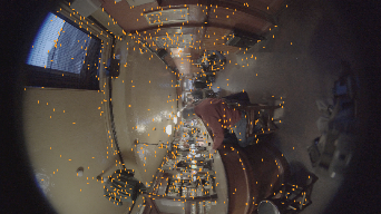
Feature matches in a single camera. |
The default alpha channel mask. |
When the rig is solved, you can also view matches between overlapping cameras in latlong space by switching the Cam Projection dropdown to Latlong.
|
|
|
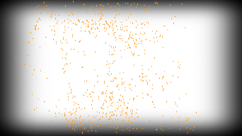
Feature matches in a single camera |
See Troubleshooting Matches and Solves for more information on improving match results.
| 6. | Click Solve to calculate the geometry for the selected rig to define the location and orientation of each camera, relative to the other cameras in the rig, and arrange the matched images in the correct order. |
Note: The solve calculates the geometry for all cameras in the rig at the same time, so there is no need to calculate them separately for left and right images in a stereo setup. See Stitching Stereographic Rigs for more information.
The solved preview image displays in the Viewer, including all matched points for the cameras in the rig.
|
|
|
|
The solved cameras and feature matches at different Viewer zoom levels. |
|
| 7. | Switch to Camera mode ( |
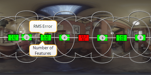
Green overlays represent RMS errors below the Error Threshold and red overlays those over the threshold.
Note: The overlay is only displayed when the playhead is on a keyframe.
See Troubleshooting Matches and Solves for information on how to refine your matched features and solve.
| 8. | Turn off the overlay by pressing Q over the Viewer to see the result. |
| 9. | The solved cameras may need a little work to get the horizon line correct before you proceed to stitching the views together. CaraVR may not automatically place your images in the correct orientation. |
CaraVR offers two methods for aligning the horizon, the Transform controls on the Settings tab and the Viewer toolbar.
• Transform Controls - Open up the C_CameraSolver Properties panel and click the Settings tab. Adjust the rotate x,y, and z controls to align the cameras as flat line halfway down the frame, or the equator.
• Viewer toolbar - enable the Horizon tool and then hold Ctrl/Cmd+Alt and drag in the Viewer to adjust the horizon line.
|
|
|
Note: You can also adjust individual cameras this way, by selecting the Camera tool instead.
| 10. | Set the required output resolution using the Format dropdown, if required. |
Tip: CaraVR adds a tab to the Properties panel of Nuke's Write node allowing you quickly select groups of views such as stereo and cams when rendering previews or stitches. You can still select views manually using the views dropdown, but View Presets can make the process faster.
| 11. | For more information about inaccurate feature matches or solved cameras, have a look at the Troubleshooting Matches and Solves section before stitching the images. |
Once you have your solved rig, you can export to a variety of preset nodes (see Exporting to Preset Nodes for more information), skip to Stitching Images Together to stitch the preview together, or proceed to C_ColourMatcher using C_ColourMatcher prior to stitching.