Generating Disparity Vectors
To generate a disparity map between two views:
| 1. | Add a C_DisparityGenerator node after the C_Stitcher. |
| 2. | Select which views you want to use for the Left View and Right View when creating the disparity map. |
| 3. | C_DisparityGenerator creates rectilinear vectors by default, but you can choose to generate Latlong vectors using the Projection dropdown. |
Latlong vectors take longer to calculate, but they allow warping across the sides of the image for spherical continuity, which can be used for motion estimation.
Setting Projection to Latlong allows you choose how vectors behave at the left and right edges of the image using the Vectorspace control:
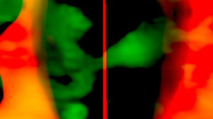
• Default (wrapped) - the vectors are simply wrapped around from left to right and right to left. This method can produce discontinuity at edges, but it's the format required by regular Nuke nodes, such as IDistort.
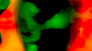
• Continuous - this method calculates vectors across the left and right edges to produce a more sensible result for use with CaraVR nodes, such as C_NewView.
|
|
|
|
Default (wrapped) shows a clear discontinuity |
Continuous eliminates the discontinuity, but |
| 4. | If there are areas in the image that you want to ignore when generating the disparity map, supply a mask either in the Mask input or the alpha of the Source input. In the C_DisparityGenerator controls, set Mask to the component you want to use as the mask. |
Note: Masks should exist in both views, and C_DisparityGenerator treats the alpha values of 1 as foreground and blurs to the 0 value using nearby disparity to recreate object boundaries, rather than image data. When you create a mask using Roto or RotoPaint, you can use the feather control to extend the calculation. For example, the disparity map may have a sharper transition at depth edges with a binary mask, but applying feather on the mask can help smooth the resulting image.
| 5. | Attach a Viewer to the C_DisparityGenerator node, and display one of the disparity channels in the Viewer by selecting it from the channels dropdown above the Viewer. |
C_DisparityGenerator calculates the disparity map and stores it in the disparity channels.
Tip: Reading depth in disparity maps can be tricky in RGB. There are a number of ways to make the depth easier to read, but the simplest is to:
1. Set the Viewer channels control to disparityL and the R layer within the channel.
2. Move the pointer around the image to locate the highest positive or negative red value using the Viewer info bar.
3. Set the gain field to +/-1 divided by the red value. For example, 1/20 for positive values or -1/20 for negative values.
4. Adjust the gain and gamma controls to reveal edges and areas of contrast.
Darker areas of the image tend to be farther away from the camera and lighter areas nearer. If you use a negative gain, the light and dark colors are flipped.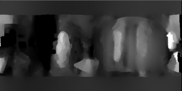
Once you've generated your vectors, you can write them out to an .exr or .sxr to combine the source image and vectors to save time later.
| 6. | You can then pass the vector data to C_NewView or C_StereoColourMatcher to replicate corrections and color between stereo pairs. See Reconstructing One View from Another and Matching Color Between Cameras for more information. |
You can also warp the image using other Nuke nodes, such as IDistort or STMap. See the Nuke Online Help for more information.