Aligning Rectilinear Stereo Images
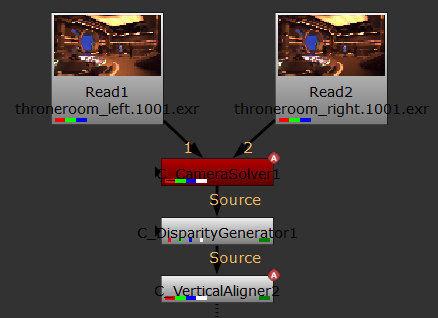
C_VerticalAligner can align rectilinear stereo images to remove vertical offset without disturbing horizontal pixel positions. C_VerticalAligner can produce results on its own as long as you don't enable Local alignment mode, but you can use C_CameraSolver and C_DisparityGenerator nodes to improve the results.
Tip: CaraVR ships with a toolset, Stereo Plate Align, containing a workflow example.
| 1. | Press S over the Node Graph to open the Project Settings or navigate to Edit > Project Settings. |
| 2. | Click the Views tab and then click Set up views for stereo. |
| 3. | Read in your rectilinear stereo images using standard Nuke Read nodes. |
| 4. | Select the clips and then add a C_CamerSolver node. |
Match and solve the images as described in Matching and Solving Cameras.
| 5. | Add a C_DisparityGenerator down stream of the C_CameraSolver. |
You don't need to adjust the controls inside the C_DisparityGenerator node, the disparity channel is calculated automatically when called from downstream.
| 6. | Add a C_VerticalAligner downstream of the C_DisparityGenerator. |
| 7. | Double-click the C_VerticalAligner node to open its Properties panel. |
| 8. | Set Camera Layout to Stereo Layout and Alignment Space to Rectilinear. |
| 9. | CaraVR automatically adds a single keyframe at the current frame, but you can add keyframes manually by either: |
• scrubbing in the Viewer and then clicking Add Key (![]() ) to add a keyframe at the current frame, or
) to add a keyframe at the current frame, or
• clicking Key All to add keyframes throughout the sequence at the Step interval.
If you have a lot of movement in your sequence, set the Step interval to a lower value so that the greater difference between frames is accounted for in the stitch. The opposite is true for more static sequences, where a higher value may produce better results.
• clicking Import and selecting the node from which you want to import keyframes. You can import keyframes from any instance of C_CameraSolver, C_Stitcher, C_GlobalWarp, C_ColourMatcher, or C_VerticalAligner in the script.
Any matches in C_CameraSolver are also imported by default. If you don't need matches from the solver, disable Import available matches.
| 10. | Click Match to calculate the vertical displacement and apply the correction specified in the Align control: |
• Both Views - aligns both views equally.
• Left to Right - align the left view to the right view.
• Right to Left - align the right view to the left view.
Note: If you set the Align control to Left or Right, you can enable the Pass-through Other View checkbox to stop the passive view being transformed, including being projected into spherical space.
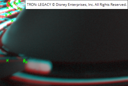
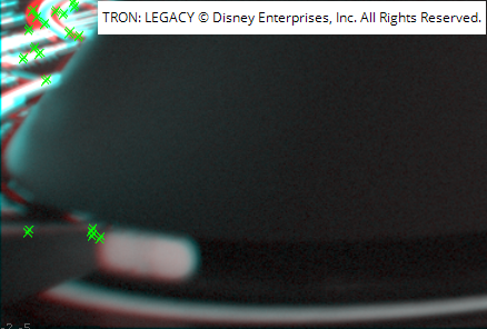
One way of reviewing the correction is to add an Anaglyph node downstream of the C_VerticalAligner and then enable and disable the C_VerticalAligner node.
|
|
|
|
Before alignment correction. |
After alignment correction. |
Refining Alignment
C_VerticalAlinger offers several types of alignment correction and refinement controls located in the Properties panel on the Settings tab.
Global Alignment
In the Global Alignment mode, C_VerticalAligner performs a global transform to align the views. You can choose between several alignment types and all methods concatenate. This means that if you select several alignment types from the Global section in the C_VerticalAligner controls, their functions are applied in the order shown in the table and combined into a single transform.
You can use the Preset dropdown to quickly enable and disable alignment options or make selections manually.
|
Camera correction |
Correct the vertical alignment for a match-move camera. If there is no camera connected, this uses the internal camera calculated by C_VerticalAligner. The correction is refined by other alignment options that are selected. |
|
Focal length |
Align the features by calculating a 2D scale to correct focal length differences. |
|
Vertical shift |
Align the features vertically by moving the entire image up or down. Calculate a 2D vertical shift to correct a global offset. |
|
2D rotation |
Align the features vertically by rotating the entire image around a point. The center of the rotation is determined by the algorithm. This helps correct in-plane camera roll. |
|
Perspective warp |
Do a four-corner warp on the images to align them on the y axis. This may move the features slightly along the x axis. Perspective warp can help correct camera tilt as well as roll. Note: A perspective change can alter pixel aspect ratio and introduce pixel skew. |
|
Vertical skew |
Align the features along the y axis using a skew. This does not move the features along the x axis. Vertical skew allows you to correct keystoning without changing horizontal disparity. This varies the vertical shift across the image without changing the horizontal position of pixels. However, this may also introduce pixel skew. |
Local Alignment
There are two modes you can use for vertical alignment. The Global Alignment method is on by default, as described above. If you enable Local Alignment on the Settings tab, CaraVR performs a local alignment in addition to the global alignment.
Local alignment rebuilds views to remove vertical disparity calculated by an upstream C_DisparityGenerator. Use this mode to create a per-pixel correction if there are any local distortions in the lens or changes in alignment with depth.
Pre-blur
The Pre-blur control allows you to set the size of the blur applied to the disparity before performing a local alignment. To smooth out the correction across depth boundaries, increase the blur size.
Correction
The Correction control allows you to set the amount of local correction to apply between the global transform at 0 and the full correction at 1. This would be useful, for example, if you want to tone down the local distortion that is applied.
Fix Scale Options
Zoom to Prevent Black in the Frame
Select the Zoom to prevent black in frame checkbox to scale the image in order to prevent pulling pixels from outside the input image. To minimize the scale, change the Align dropdown to Both Views.
Warning: The scale has to be applied to both images, even when aligning Left to Right or Right to Left.
Calculate Scale
The Calculate scale control allows you to calculate the scale at the current frame. If the alignment options change, the scale needs to be recalculated. You can lock the scale correction to prevent any changes by selecting the Lock scale checkbox.
Scale
The Scale control allows you to set the global scale that is applied to prevent black in the frame. You can set a key to interpolate the scale calculated at different frames.
Warning: Animating the Scale control creates a dynamic zoom on the shot, which may not be the stereographer's original intent. In this case, it is recommended to use a static zoom from a single frame, to preserve the original intent of the shot.
Fix Offset Options
Preserve Subject Parallax
Select the Preserve subject parallax checkbox to shift the image in a way that preserves the parallax at the specified Fix Point. This requires the input to have disparity vectors. If disparity vectors do not already exists, you need to add an O_DisparityGenerator node upstream of O_VerticalAligner.
Fix Point
You can move the Fix Point to sample the input disparity and update the applied offset to preserve the parallax. View the output of O_VerticalAligner to set the Fix Point when the Output is set to Image. You can lock this to prevent any changes by selecting the Lock offset checkbox.
To change the Fix Point, drag the fixPoint widget from the bottom-left corner of the Viewer and drop it in the new position. Disparity is then recalculated according to the new Fix Point. You can also use the user matches determined by O_Solver to set the Fix Point.
Offset
You can use the Offset control to set the correction in pixels, that is applied to prevent parallax changes at the Fix Point. To interpolate the offset calculated at different frames, set a key.
Note: Note that you can re-converge the views after you have aligned the plates to preserve depth.