Embossing Surface Strips with MeshFusion
You can create embossed strips on Fusion Items using Curves, Beziers, B-Splines, or text.
Creating Embossed Strips with Flat Curves
To create embossed strips using curves, you need to create surface strips on a Primary mesh using a Trim mesh.
Note: To learn more about mesh roles in MeshFusion, see Mesh Roles and Relationships.
- Add a mesh and create a new Fusion Item, as described in Creating a New Fusion Item.
Your mesh item becomes a primary and it's marked with green in the Item List and the 3D viewport. A Fusion Item is also created. - To produce a flat curve in an ideal position for creating surface strips, place the cursor in the center of your primary mesh and press Alt+O on the keyboard. This moves the Work Plane to that location, and your curves will be drawn in that position.
- In a new mesh layer, create the geometry you want to use as the trim for the surface strip.
The following example uses a shape drawn with a B-Spline, but any of the standard Curve tools can be used (Curve, Bezier).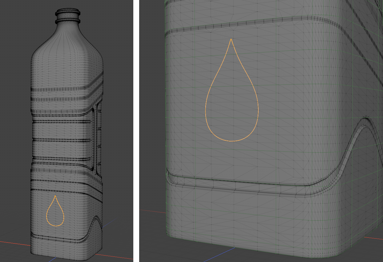
- In the Item List, select your Curve mesh and Primary mesh. Then in the modeling toolbar's Fusion sub-tab on the left, under Apply Surface Strip, click the Full Strip with Grid Crossing
 button.
Surface strips are created on your Primary mesh, and your Trim mesh is marked with pink in the Item List.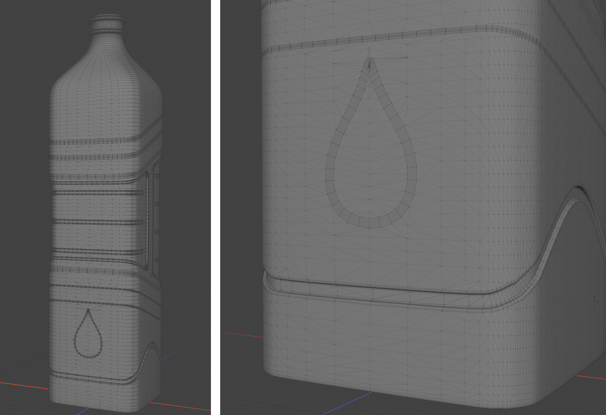
Note: If you haven't edited the Strip Width when creating the Fusion Item, the default 1mm is used. To increase the width: select your Trim mesh in the Item List to open its Properties, then adjust the Mesh Fusion > Surface Strip Absolute Width value. In the example above, strip width is 2mm.
If your Fusion Item is set to use relative strip width, this property has no effect on the strip width, instead, it is controlled by the Fusion Item property Default Strip Settings > Strip Width. - In the Items list, select your Fusion Item to open its Properties panel, and under Fusion properties, enable Enable Embossing.
- Select the Trim mesh in the Item List to display its Properties panel.
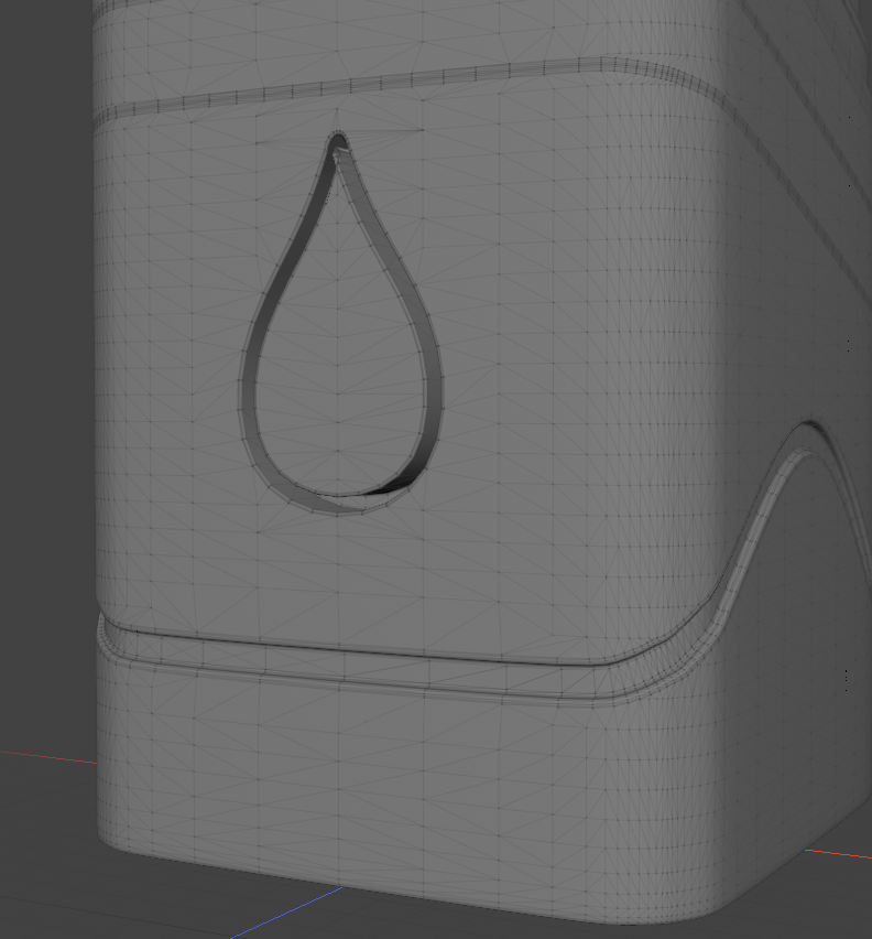
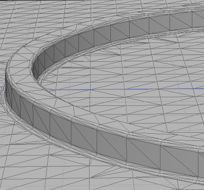
- Under Mesh Fusion Embossing properties, enable Enable Embossing and edit the Outward, Inward, and Middle Offset values. The embossing is now visible in the 3D viewport.
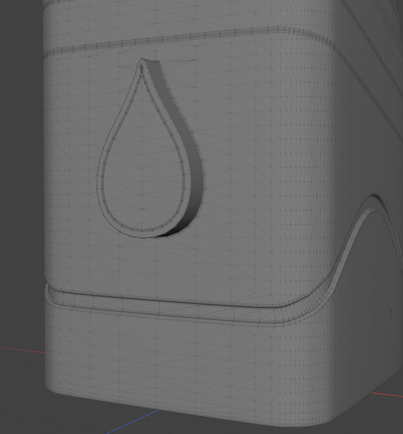
Middle Offset: 2mm
Inward and Middle Offset: 2mm
A negative offset will emboss in the other direction.
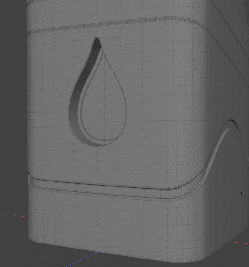
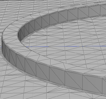
Middle Offset: -2mm
Inward and Middle Offset: -2mm
Tip: When working with Bezier curves, you might have sharp corners on your curve. In such cases, enable Sharp Bezier Corners to produce clean strips for embossing.
Note: If the outward patch interacts with another regular strip as well as the embossed one, you must leave Outward Offset at 0, as offsetting a regular strip is not currently supported and would produce unexpected results.
Intersections between embossed surface strips and regular surface strips are not currently supported either.
Working with Curves within Curves
When creating embossing using one loop within another, the direction of the curve is important in specifying the outward and inward patches. When both curves are drawn in the same direction, the inward area for the outer curve is the outward area for the inner curve. This will produce unexpected results for embossing.
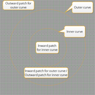
Draw your outer curve clockwise, and your inner curve counter-clockwise. Alternatively, you can flip your curves after the fact. To do this, in Polygons selection mode, select your curve, and press F on the keyboard. This flips the direction of the curve.
Note: When drawing loops side by side, make sure they are drawn in the same direction, so their outward and inward patches match.
Creating Embossed Strips with Non-Flat Curves
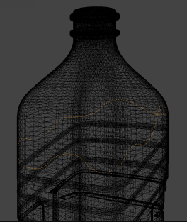
Instead of drawing your curve on the Work Plane, you might want to draw them on the primary surface. When you do this, curves are not flat, but follow the surface of the object, going around it.
Note: Make sure you don't have any intersecting curves.
- Add a mesh and create a new Fusion Item, as described in Creating a New Fusion Item.
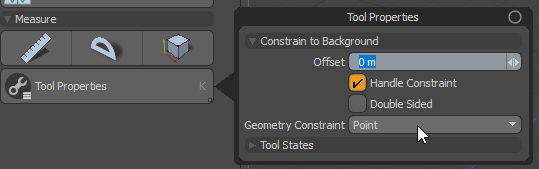
A Fusion Item is added to the Items list and your primary mesh is marked with green. - In an empty mesh layer, enable Mesh Constraint.
When enabled, the Tool Properties appear on the lower left. - In the Tool Properties, enable Handle Constraint and set Geometry Constraint to Point.
- Select your empty mesh layer and draw a curve that you will use as the trim for the surface strip.
Note: Your Primary mesh must be visible in the viewer for the constraint to work correctly.
- In the Item List, select your Curve mesh and Primary mesh. Then in the modeling toolbar's Fusion sub-tab on the left, under Apply Surface Strip, click the Full Strip with Grid Crossing button.
Surface strips are created on your Primary mesh, and your Trim mesh is marked with pink in the Item List. - Select the Trim mesh in the Item List to display its Properties panel, and set the following:
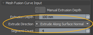
• Set the Extrude Direction. For non-flat curves, the default Extrude Perpendicular to Curve option doesn't produce correct results. Select your curve mesh, and in the Properties panel, under Mesh Fusion Curve Input, set Extrude Direction to Extrude Along Surface Normal.
• Under Mesh Fusion Embossing properties, enable Enable Embossing and edit the Outward, Inward, and Middle Offset values.
Note: If the outward patch interacts with another regular strip as well as the embossed one, you must leave Outward Offset at 0, as offsetting a regular strip is not currently supported and would produce unexpected results.
Intersections between embossed surface strips and regular surface strips are not currently supported either.• When working with Bezier curves, you might have sharp corners on your curve. In such cases, enable Sharp Bezier Corners to produce clean strips for embossing.
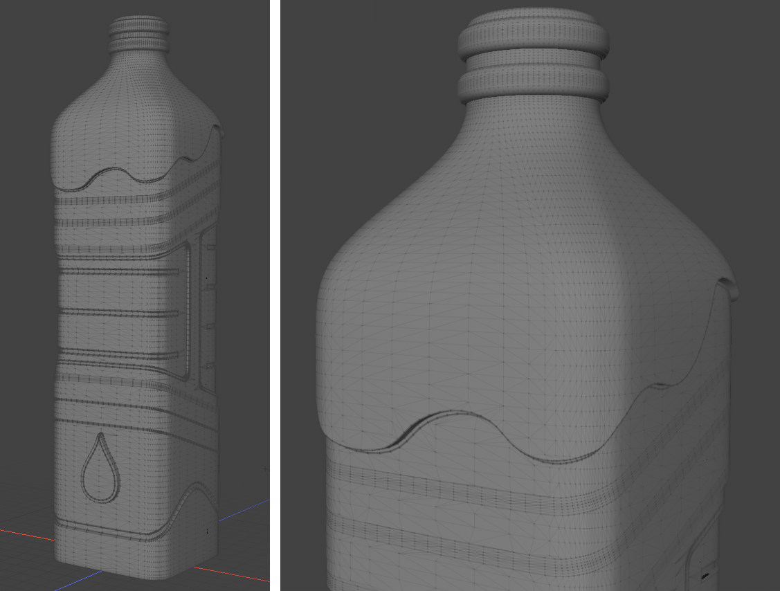
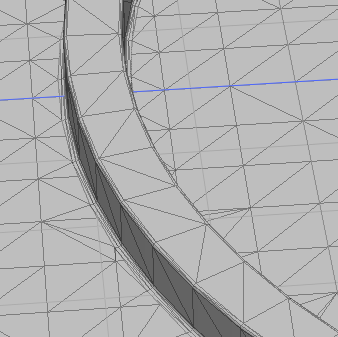
Setting Inward Offset to 2mm gives you the following result:
Using the Fusion Deformer
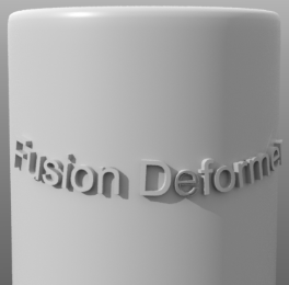
The Fusion Deformer workflow allows you to deform flat curves to follow curved surfaces.
First, a flat 2D curve is deformed to become a 3D curve embedded into a curved surface. Then the 3D curve is used to create embossing on that surface, the same way as when the 3D curve is drawn on the surface manually, as described in Creating Embossed Strips with Non-Flat Curves.
This method is particularly suitable for slapping text strings onto curved surfaces, or deforming 2D drawings.
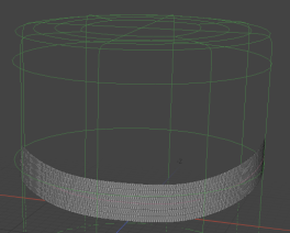
Creating the Strip
First, create a regular surface strip setup:
- Add a mesh and create a new Fusion Item, as described in Creating a New Fusion Item.
Your mesh item becomes a primary and it's marked with green in the Item List and the 3D viewport. A Fusion Item is also created. - Hide the Fusion Item by clicking its Visibility
 button in the Item List, to make it easier to see the curve you're going to draw.
 - In an empty mesh layer, enable Mesh Constraint, then in the Tool Properties on the lower left, enable Handle Constraint and set Geometry Constraint to Point. This is to make sure that the points of the curve don't fall too far away from the mesh for strip embossing to work.
- Draw an open curve in the empty mesh layer that you will use as the trim for the surface strip. You can use any of the standard Curve tools (Curve, Bezier, or B-Spline). For more information, see Adding Curves.
- Drop the curve tool, disable Mesh Constraint, and make the Fusion Item visible again.
- In the Item List, select your curve mesh and Primary (green) mesh, then under Apply Surface Strip, click the Full Strip with Grid Crossing button.
Surface strips are created on your Primary mesh, and your Trim mesh is marked with pink in the Item List.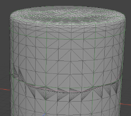
- Now you have to make some modifications to how the strip is created. Select your curve mesh to open its Properties, and under Mesh Fusion Curve Input > Extrude Direction, select Extrude Along Surface Normal.
Note: The default Extrude Perpendicular to Curve option produces incorrect results with non-flat curves.
- Set the width of the surface strip. Still in the curve mesh Properties, under MeshFusion > Mesh Properties, set the Surface Strip Absolute Width.
Make sure that the strip is wide enough to fit the text string or drawing you are going to emboss. You can always change the width later. The example below uses a strip width of 180mm.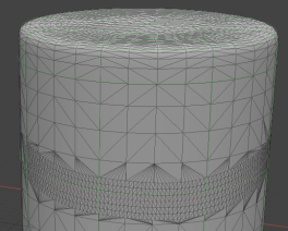
- The strip mesh must be dense and uniform along the strip. To achieve this, select your Fusion Item to open its Properties, and under Global Strip Settings, enable Abs Strip Quad Length.
The default Strip Length Abs of 10 mm is fine for models of about 1 meter size. Generally, about 1/100 of the model size works well.
Note: Wider strips tend to develop kinks where the guiding curve makes a turn. If the strip mesh self-overlaps, this may create problems at later stages. To smooth out kinks, increase the value in Default Strip Settings > Strip Smoothing in the Fusion Item Properties.
Tip: You can declutter your scene by enabling Fusion Mesh > Strip Polys Only, since here we only care about the surface strip mesh, not the surrounding primary surface mesh.
Adding Text
Once the strip is ready, it’s time to create the flat 2D curves that will be deformed by the strip. This example uses Bezier curves created by the Text mesh operation.
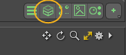
To use the Text mesh operation, open the Mesh Operations list. In the Modo layout, you can do this using the top viewport controls. Click on the bar above the 3D viewport to reveal the controls, then click the Mesh Operations viewport button:
- In an empty mesh, create a Text mesh operation.
When the mesh operation is added, its properties are displayed in the Properties tab on the right. - In the Properties, edit the Text, Font, and Size. Set Output Type to Bezier, Location to Middle, and Justification to Left.
Note: With left justification, the text is positioned to the left end of the text string in the world coordinate system origin. That point corresponds to the start of the strip, and the text string flows from the start of the strip to the end.
Vertically, Y = 0 corresponds to the middle of the strip, which is why you would typically set Location to Middle.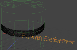
- Add the text item to the Fusion as a Primary: select the text mesh and your Primary (green) mesh, and in the Fusion sub-tab on the left, under Set Mesh Role & Apply, click the Apply Primary
 button.
The text mesh is marked as a Primary mesh in the Item List, but nothing happens in the 3D viewport yet. - Select the Fusion Item and in its Properties, enable Fusion Deformer.
The strip mesh is replaced by the deformed text string.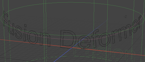
- If you need to adjust the text, you can use the handles in the 3D viewport. To display them, select the Text mesh operation in the Mesh Operations list. If you need to edit the strip length, make sure to disable Fusion Deformer so you can see the strip you're editing.
So far, we've created the deformed text curve that follows our primary surface. To use it for embossing that primary surface, we need to create another instance of MeshFusion which will use the deformed curve output from our first instance of Fusion as input.
Creating the Embossing
To emboss our text, we need to create another Fusion Item.
- In a new mesh layer, add a Merge Meshes mesh operation.
Note: For more information on how to do this, see Merge Meshes.
- Expand the mesh operation in the list, and under Sources, click (Add Sources) to add the Fusion Item.
Now our deformed curve appears as a separate item in the Item List.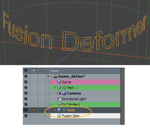
-
Select the Primary surface on which embossing is to appear, and in the Fusion sub-tab, under Duplication, click the Duplicate as Non-Fusion Mesh
 button.
This duplicates your Primary mesh as a non-Fusion item. - Click New Fusion to create a second Fusion Item from the primary mesh.
A second Fusion Item is created. - Select the duplicate Primary and the newly merged mesh that contains your deformed text, and in the Fusion sub-tab, under Apply Surface Strip, click the Full Strip with Grid Crossing button.
Surface strips are generated on the Primary surface, and the curve mesh is marked with pink to indicate that it's a Trim. - Select only the deformed curve mesh and in its Properties, under MeshFusion Curve Input, set the following:
• Extrude Direction to Extrude Along Surface Normal.
Note: To determine the outward and inward patches for embossing, MeshFusion expects the outer loops to be drawn clockwise and the inner loop counter-clockwise. For certain fonts, this is the other way around, and as a result, Extrude Along Surface Normal produces incorrect results. To correct this, in the Text mesh operation's properties, enable Flip.
• Under MeshFusion, change Fusion SubDivs from default 2 to 0.
• Under MeshFusion Embossing, check Enable Embossing, and set Middle Offset and Outward Offset to the desired values.
Note: Surface strips created from Bezier curves with sharp turns don't typically work well, as they self-overlap on the turns. You can fix this by enabling MeshFusion Embossing > Sharp Bezier Corners in the section of the deformed curve's Properties.
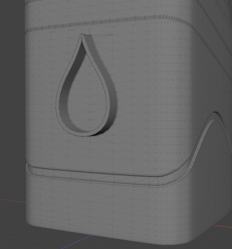
- In the second Fusion Item's Properties, check Enable Embossing.
Embossing appears in the 3D viewport.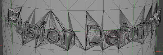
Case Study: Fixing Missing Surfaces in Fusion Models
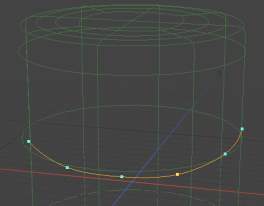
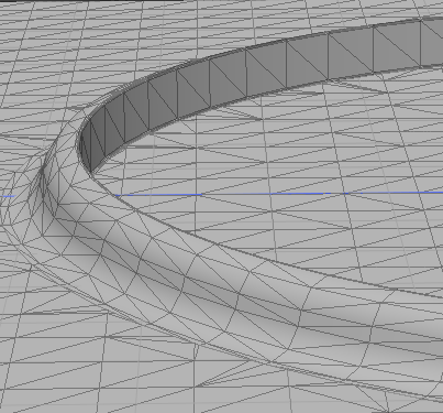
Lets look at a Mesh Fusion scene which has issues with Fusion surfaces and curve meshes disappearing and walk you through how these issues can be fixed. In the following image, something is wrong.
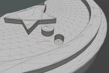
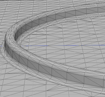
The sidewall of the small cylinder has inverted normals, and there is no cap on the cylinder. This is because the cylinder Bezier curve was drawn in the clockwise direction instead of counterclockwise. With the curve item selected in the Items list and Polygon selection mode active, we click on that curve loop and press F to flip the loop. In the following image, the result is correct.
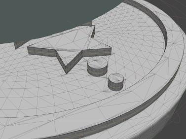
Tip: The rule is that the outward normal is pointing to the right as you draw the bezier curve. If you want a positive island like this example with the normal facing outward, you need to draw the curve counterclockwise. If you want a hole with the normal facing inward, draw the curve clockwise.
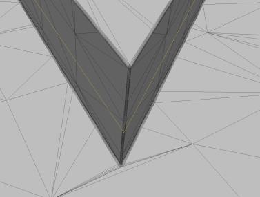
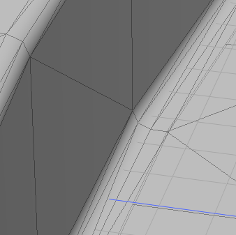
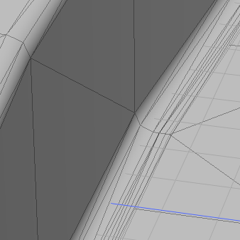
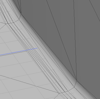
The following image shows the next problem with sharp corners.
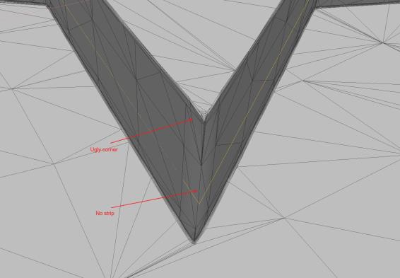
An issue like this indicates that Sharp Bezier Corners is not enabled. With the curve selected in the Items list, enable Sharp Bezier Corners in the Properties. Once enabled, the corner is clean.
Another issue occurs when we select the mesh we want to use to cut into the main mesh, then click Apply Subtractive Trim in the Fusion tab, then select the cutting mesh and the rest of the curves in our scene and click Trim. The output mesh disappears from our scene.
We have two primary meshes in the scene. The main primary mesh (the base disk seen in the image) and the mesh extruded from curves. The extruded mesh grows upward from the disk.
The extruded mesh is unusual because it has open edges. You cannot make a closed surface by extrusion. When using open edges in a system like Mesh Fusion, which creates models by intersecting surfaces, you need to be careful not run into open edges when intersecting surfaces.
The reason why our Mesh Fusion failed in this scenario and the mesh disappeared is because the main primary mesh has two trims applied - a curve and the cutting mesh. However, the main primary mesh has only one trim applied, which is the cutting mesh.
Because of this, Mesh Fusion cannot perform a union between the two primaries first, so it applies the trims separately to the mesh extruded from curves and the main primary mesh. Because the mesh extruded from curves is a mesh with open edges, and our cutting mesh reaches deep enough to run into these open edges, the operation fails and the output mesh does not appear.
The fix is to make the main primary mesh use both trims, just like the curves mesh. All we need to do is select the main primary mesh and the curve and click Trim in the Trim/Untrim section of the Fusion tab.
Tip: A general rule to follow is whatever trim you apply to your curve meshes, apply the same trims to your primary mesh which serves as the base for the curve mesh. This allows Mesh Fusion to weld the extruded mesh and the base primary together before applying any trims, thus avoiding the open edge problems.
Embossing Properties
Mesh Fusion Embossing
|
Enable Embossing |
When enabled, surface strips are embossed, using the Outward, Inward, and Middle Offset values. |
|
Sharp Bezier Corners |
Sharp corners on Bezier curves can result in incorrect strip geometry. When enabled, strips on sharp Bezier corners end and a new one begins. |
|
Outward Offset |
The amount by which the area outside the curve is offset. |
|
Inward Offset |
The amount by which the area inside the curve is offset. |
|
Middle Offset |
The amount by which the area within the curve is offset. |
Mesh Fusion Advanced Embossing
|
Apply Embossing Preset |
Instead of directly editing the values, embosses the curve using a preset. The following options are available:
|
||||||||||||
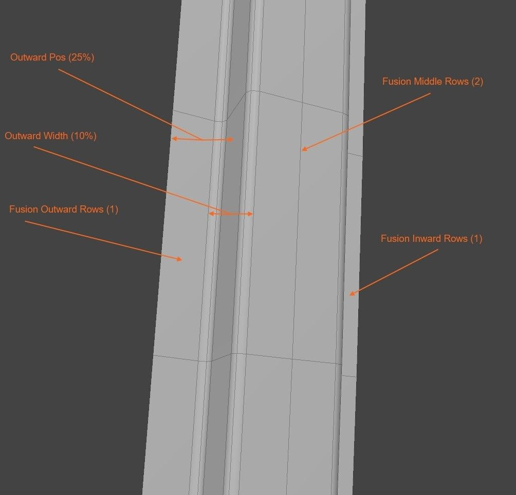
|
Fusion Middle Rows |
Sets the number of polygonal rows that make up the middle section of the strip. The default and minimum value is 1.
|
||||||||||||
|
Fusion Inward Rows |
Sets the number of polygonal rows on the inner shoulder. The default and minimum value is 1.
|
||||||||||||
|
Fusion Outward Rows |
Sets the number of polygonal rows on the outer shoulder. The default and minimum value is 1.
|
||||||||||||
|
Inward Position |
Adjusts the width of the strip from the inward patch to the middle of the strip. a setting of 0 uses the full length of the Surface Strip Absolute Width. Increasing this value decreases the width of the strip from the inside. |
||||||||||||
|
Outward Position |
Adjusts the width of the strip from the outward patch to the middle of the strip. a setting of 0 uses the full length of the Surface Strip Absolute Width. Increasing this value decreases the width of the strip from the outside. |
||||||||||||
|
Inward Width |
The width of the entire rounding area, from where the rise starts on the shoulder on the inside to where it ends at the beginning of the flat top, in the horizontal direction. |
||||||||||||
|
Outward Width |
The width of the entire rounding area, from where the rise starts on the shoulder on the outside to where it ends at the beginning of the flat top, in the horizontal direction. |


The image below shows you the parts of an embossed Fusion strip: