Snaps and Precision Palette
The Snaps and Precision Palette provides a handy floating palette that holds all the settings and tools related to snapping in a single viewport. You can open it from the menu bar by clicking Edit > Snapping > Snaps and Precision.
The palette includes several tool options you can use for precision transforms. Created with the power of the Tool Pipe, they are automated combinations of transform actions, snap settings and Specifying Action Centers and Falloffs .
Tip: Once opened, the visibility of all floating palettes can be toggled on and off by pressing the ` (backtick) key.
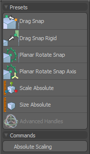
Snaps and Precision Palette - Presets
|
Drag Snap |
This tool combines the Element Move transform with Geometry Snap. This allows components of a mesh to be quickly dragged and snapped to other components in the project. By default, the Element Move transform is set to Auto, which allows you to click and drag a vertex, edge or polygon regardless of the current selection mode. See Using Falloffs and Applying Snapping for more information. |
|
Drag Snap Rigid |
This tool is very useful for moving connected geometry by dragging it from a single component such as a vertex, edge or polygon. The tool combines with snapping, so that you can quickly snap the current component to another component in the project while dragging the rest of the connected polygons along in a rigid manner. |
|
Planar Rotate Snap |
This tool is excellent for precisely aligning elements. To use the tool, click on any component in the scene. This determines the element upon which the tool handles are centered. Next, use the outermost handle to establish the resting orientation for the rotation control by dragging that handle to any component in the project. The handle snaps to vertices, edges or polygons. Once the rest orientation has been determined, use the inner round handle to apply some rotation. This rotation action can be freehand or you can once again leverage geometry snapping to very accurately set the rotation. |
|
Planar Rotate Snap Axis |
This tool is similar to the Planar Rotate Snap tool with the extension of a second axis handle for controlling the plane of rotation. This is an advanced tool that is invaluable in certain complex rotation scenarios that require absolute precision. Like the Planar Rotate Snap tool, the first click sets the center and axis for the tool based on the component under the mouse. |
|
Scale Absolute |
This combines the Scale tool (Absolute Handles option active) with the Geometry Snap modifier. The tool utilizes a two step process. In the first step you use the Absolute handles to set the starting scale point for the tool. Next you use the Scale handles to actually modify the geometry. During both steps, the handles can snap to the geometry, thus allowing you to use one mesh component to set the initial scale and a second component to create the Absolute scale. |
|
Size Absolute |
This option opens an absolute sizing option. |
|
Advanced Handles |
This option toggles the visibility of Advanced handles for the selected tools. This often places additional controls into the screen viewport making it easier to produce more accurate results. |
Commands
|
Absolute Scaling |
Clicking the Absolute Scaling button of the Snaps and Precision palette opens another palette with a useful set of utilities that allow you to explicitly define a size and scale on an item's bounding box and modify the center axis position when assigning the transform. |
|
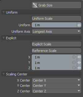
Grab Size |
This command grabs the actual bounding box size and inputs it into the Uniform and Explicit data fields as a point of reference for sizing the selection. |
Uniform
The Uniform Scale options provide a means to uniformly scale all axes of a selection in a single step. To use, first choose the Grab Size command. This captures the longest axis length and inserts it into the Uniform value input field as a point of reference. Next, select a scaling center if you want it to be other than the default bounding box center. Enter a new explicit value into the Uniform input field. In Uniform Axis, define the axis you wish to scale absolutely, and then finally click the Uniform Scale button to perform the scale operation.
|
Uniform Scale |
Uniformly scales the bounding box for the selected item by the value in the Uniform input field, based on the Uniform Axis field. |
|
Uniform Axis |
When scaling the bounding box, Uniform Axis determines on which axis the scaling command operates, with the other two axes scaled in proportional amount in relation to the defined axis. |
Explicit
The Explicit Scale option provides a means to define a specific size to the bounding box of the selected elements. To use it, first choose the Grab Size command. This captures the bounding box volume size of the entire selection. Next, select a scaling center if you want it to be other than the default bounding box center. Enter new size values into the X,Y and Z input fields, and click the Explicit Scale option to scale the object to the specified size.
|
Explicit Scale |
Scales the bounding box for the selected item by the value in the X,Y and Z input fields. |
|
Reference Scale |
The selected section of geometry (assuming it's a smaller section of a whole) defines the scaling amount as a reference, but all connected geometry is scaled proportionately to the selected area. For instance, if you know the size of the cockpit of a race car, you can scale the entire car by the proportional amount based on just the selected cockpit area. |
Scaling Center
|
Scaling Center X/Y/Z |
When scaling a selected area, these values define the origin of the scaling operation as defined from the drop-down selection. The Low option defines the side toward the negative end of the axis, Center refers to the averaged center position of all vertices, and High is the side of the bounding box nearest the positive values of the axis. |