Search is based on keyword.
Ex: "Procedures"
Do not search with natural language
Ex: "How do I write a new procedure?"
Katana Quick Start Guide
The primary user interface in Katana is the Node Graph tab, where you add nodes to your recipes in order to create, import, or manipulate objects and shaders. Nodes have editable parameters, and are interconnected, passing data from node-to-node along the connections. The flow of data is one-way (downstream), with the output of one node passed as an input to its downstream neighbor (or neighbors).
The node graph itself is not what Katana sends to the renderer. Instead, Katana constructs a scene graph of scene data from the contents and interconnections of the node graph, and it's this scene graph data that is sent to your renderer.
1. Learning About the Node Graph, Recipes, and Node Creation
| 1. | Hover the mouse over the Node Graph tab and press Tab. |
All available nodes are displayed.
| 2. | Type PC. |
This narrows the node list down to those with PC at the start of their name and those with PC as their name’s starting capital letters.
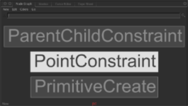
| 3. | Click PrimitiveCreate. |
The PrimitiveCreate node is selected. Once selected, it floats with the cursor, ready to be placed.
| 4. | Click somewhere towards the top of the Node Graph. |
The node is added to the Node Graph, beginning a new recipe.
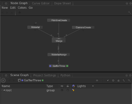
The Node Graph is where it all starts. It is here that you create a recipe by connecting various nodes, which add, override, or modify scene data.
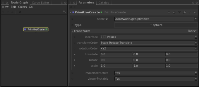
Most recipes start by reading in the 3D elements - such as camera data, geometry caches, or particle caches - that comprise the scene. In this example, we use a PrimitiveCreate node that defaults to a sphere.
One of the most important things to understand about the Node Graph, and its resulting recipe, is that it is non-destructive. The recipe is a description of how to bring in the ingredients (the various assets), modify them to suit the shot, add materials and assign them to objects, add lights, and finally send everything off to a renderer. The recipe approach is extremely flexible, allowing the assets to be continually updated in an iterative workflow.
For more on nodes and the node graph, see Editing the Node Graph.
2. Editing a Node and Using the Parameters Tab
Hover the mouse over the PrimitiveCreate node and press E.
A green square displays at the right-hand side of the node and the node’s parameters are displayed in the Parameters tab.
This is one way to make a node editable. You can also:
• select one or more nodes and press Alt+E, or
• click the faint square at the right-hand side of the node.
Most nodes within Katana have parameters that modify their behavior. You can change these parameters in the Parameters tab. A node that is being edited within the Parameters tab displays a green square on its right-hand side.
To find out more about parameters and the Parameters tab, see Editing a Node’s Parameters.
3. Creating and Assigning Materials
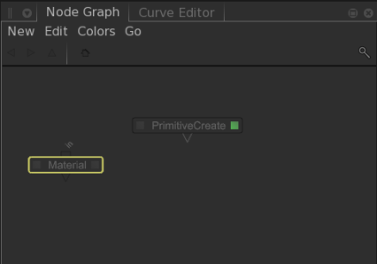
| 1. | Press Tab in the Node Graph. |
| 2. | Type MAT to filter the node list. |
| 3. | Select Material. |
| 4. | Click to the left of the PrimitiveCreate node to add the Material node to the Node Graph. |
| 5. | Hover the mouse over the Material node and press E. |
The Material node becomes editable within the Parameters tab.
| 6. | In the Parameters tab, click Add shader and select a shader type from the list, in this case dl Surface. |
The shader list varies depending on the renderers installed.
| 7. | Click the large dropdown to the immediate right of the shader type and select a material3Delight shader. |
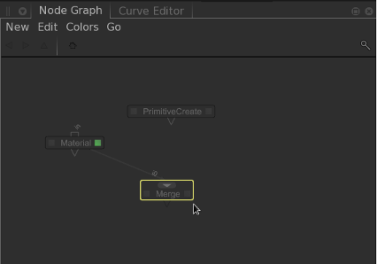
| 8. | Create a Merge node and place it below the PrimitiveCreate node. |
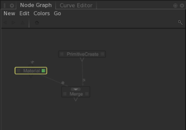
| 9. | Hover the mouse over the Material node and press ‘ (Backtick). |
A connection from the Material node is started.
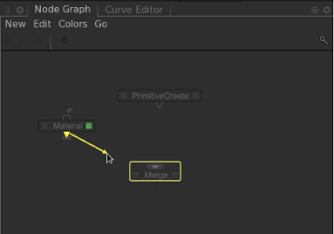
| 10. | Hover the mouse over the Merge node and press ‘ (Backtick). |
Pressing Backtick a second time connects the Material node to the input of the Merge node. It is also possible to manually connect two nodes by dragging from the output triangles to the input squares, see Connecting Nodes.
| 11. | Connect the PrimitiveCreate node to the Merge node, as described above. |
The Merge node brings different branches of the recipe together, combining their scene data. Right now, the Merge node brings together the sphere created by the PrimitiveCreate node and the material created by the Material node.
| 12. | Create a MaterialAssign node using the Tab menu. |
| 13. | With the MaterialAssign node floating with the cursor, hover the node over the output from the Merge node until it turns yellow, then click to connect. |
This connects the MaterialAssign node to the output of the Merge node. The MaterialAssign node continues to float with the cursor.
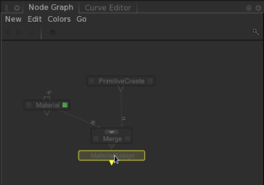
| 14. | Click below the Merge node to place the MaterialAssign node. |
| 15. | Hover the mouse over the MaterialAssign node and press E. |
The MaterialAssign node becomes editable within the Parameters tab.
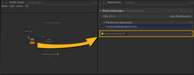
| 16. | Shift+middle-click and drag from the PrimitiveCreate node to the Add Statements menu in the Parameters tab. |
The scene graph location of the object created by the PrimitiveCreate node is added to the CEL parameter.
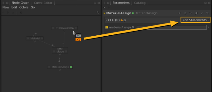
After you’ve created a material it needs to be assigned. In the MaterialAssign node, Katana uses the Collection Expression Language (CEL) to create a list of scene graph locations to be used in the material’s assignment.
For a more comprehensive explanation, and an explanation of locations, see Using the Scene Graph.
For further details on CEL, see Assigning Locations to a CEL Parameter.
| 17. | Shift+middle-click and drag from the Material node to the materialAssign parameter in the Parameters tab. |
An expression is created that links the material created by the Material node to the materialAssign parameter. If the location created by the Material node changes, the expression automatically updates the materialAssign parameter with the new location.
Materials define how geometry and lights are rendered. Each material can have one or more shaders for each renderer, as well as a shader that defines how that object is displayed in the 3D Viewer. Materials can be assigned to geometry or lights and then saved as a Katana Look File (.klf). This part of a production pipeline is commonly referred to as look development.
Katana Look Files are extremely powerful. For a more in-depth explanation, see Look Development with Look Files.
4. Lights, Camera, Action
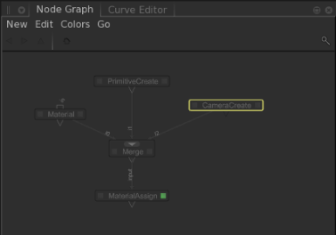
| 1. | Create a CameraCreate node in the same way as the previous nodes and place it to the right of the PrimitiveCreate node. |
| 2. | Connect the CameraCreate node to the Merge node. |
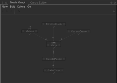
| 3. | Create a GafferThree node and connect it to the output of the MaterialAssign node. |
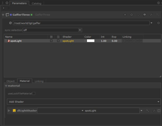
| 4. | Hover the mouse over the GafferThree node and press E. |
The GafferThree node becomes editable within the Parameters tab.
| 5. | Right-click on the gaffer object table in the Parameters tab and select Add > spotlight or hit the keyboard shortcut Q |
This creates a 3Delight spotlight and places it in the gaffer object table.
In the example, the camera is created within the recipe. It could just as easily be brought in from an external file, such as Alembic (ABC). Supplementary cameras may be placed in Katana for various rendering techniques, such as camera based projections or stereo.
Lights are usually created within the GafferThree node. The name comes from the role of the person on-set responsible for the setting up of the lights - the Gaffer. The GafferThree node provides a one-stop-shop for a number of convenient lighting functions, for instance: light creation, shader assignment, and light soloing and muting.
For more information on the GafferThree node, see Getting to Grips with the GafferThree Node or, for lighting in general, see Lighting Your Scene.
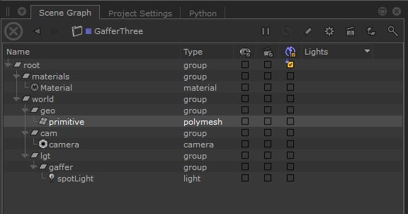
5. Using the Scene Graph
| 1. | Hover the mouse over the GafferThree node and press V. |
The Scene Graph tab now displays the 3D scene generated up to the GafferThree node.
This is one way to view the scene graph generated at a node. You can also click the faint square at the left-hand side of the node.
When the Scene Graph tab is displaying the scene generated at a node, that node (referred to as the view node) has a blue square displayed on the left-hand side.
| 2. | In the Scene Graph tab, right-click on the /root location and select Expand All. |
The /root location expands to display everything within the scene graph.
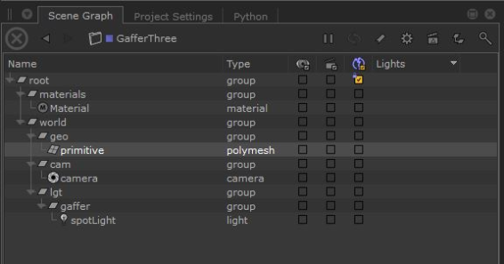
There are a few key concepts regarding the scene graph:
The first key concept is that: the Scene Graph is just a viewer. The scene graph displays the 3D scene generated for the current frame by stepping through the recipe up to the node with the blue square - this node is the current view node.
The second concept is that: there is no such thing as the scene in Katana. You can merge and branch the recipe, pruning and adding to one of the branches. Therefore, pressing V at different nodes can generate vastly different scenes. To see this for yourself, hover the mouse over the CameraCreate node and press V. The scene graph changes because at this node in the recipe, only the camera has been created. You can view the 3D scene generated at any of the other nodes in the same way. When you are happy, hover the mouse back over the GafferThree node and press V again.
Lastly, the Scene Graph only loads data as it is needed. This deferred loading makes it possible for Katana to contain recipes dealing with scenes of incredible and potentially even infinite size. As you control which elements are loaded - by expanding locations within the scene graph - you can light extremely complicated scenes by only loading the required data. You don’t need to load all the scene data to light the scene.
Each location, such as /root or /root/world, within the scene graph has attributes that you can view within the read-only Attributes tab. To find out more about the scene graph, locations, and attributes, seeUsing the Scene Graph.
There are three main viewers for the underlying scene graph data in Katana, the Scene Graph tab, the Attributes tab, and the Viewer tab.
Locations in the scene graph have attributes, which are determined by parameters on nodes in the node graph. For example:
| 1. | Add a PrimitiveCreate node to an empty Katana project. |
| 2. | Edit the node's parameters so that it's a type sphere, scaled to 3.0 in each of the X, Y, Z axes. |
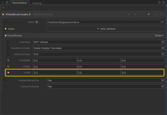
Katana creates a sphere primitive in the scene graph from the information in the PrimitiveCreate node in the node graph. Select the primitive location in the Scene Graph tab and look at its Attributes tab.
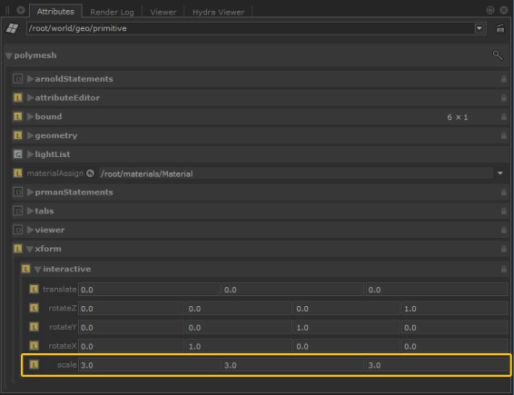
| 3. | Under xform.interactive the scale is set to 3.0 in each of the X, Y, Z axes. Go back to the PrimitiveCreate node in the Node Graph and enter a Z scale value of 5.0. |
Now go back to the primitive location in the scene graph and see that under xform.interactive, the Z scale has changed to 5.0.
6. Using the Hydra Viewer
| 1. | With the GafferThree node as the view node (designated by the blue square) and the scene graph fully expanded, select primitive in the Scene Graph tab. |
| 2. | Towards the bottom of the Hydra Viewer tab (located in the bottom-right pane by default), click  . . |
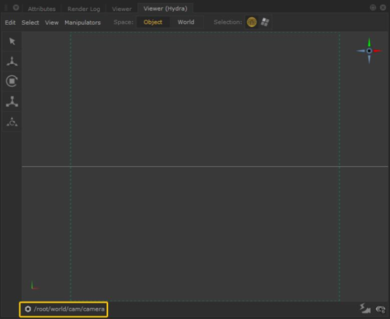
You see a list of objects you can look through.
| 3. | Select ../camera. |
The Hydra Viewer tab now shows the view from the point of view of the camera.
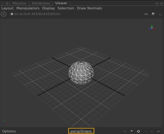
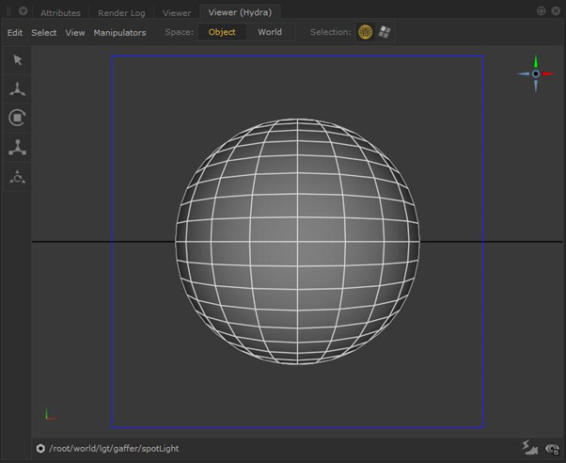
| 4. | With primitive still selected in the Scene Graph tab, press F in the Viewer tab. |
The camera moves to frame the currently selected object and makes it the camera’s point of interest.
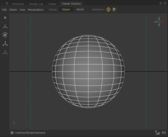
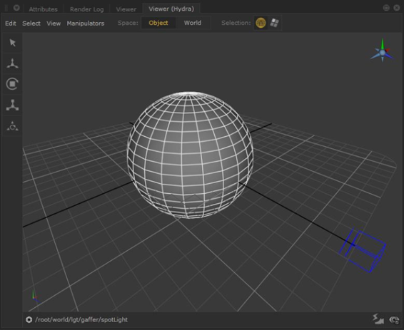
| 5. | Click ../camera in the Viewer tab and select ../light. |
The view changes to that of the light.
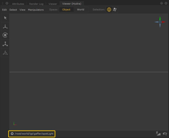
| 6. | Press F in the Viewer tab to frame the sphere again, this time for the light. |
| 7. | Alt+left-click and drag to rotate the light around the sphere and position the light. |
The Viewer is a 3D representation of the scene within the scene graph but only locations exposed within the Scene Graph are displayed. Therefore, if you first view the scene graph for a node and only /root is exposed the Viewer is empty.
To learn more about how to move around and manipulate objects within the Viewer, see Using the Hydra Viewer.
7. Starting a Render
Katana has a number of render options, and their availability depends on the type of node you try to render from. For the render options available at each type of node, see Rendering Your Scene.
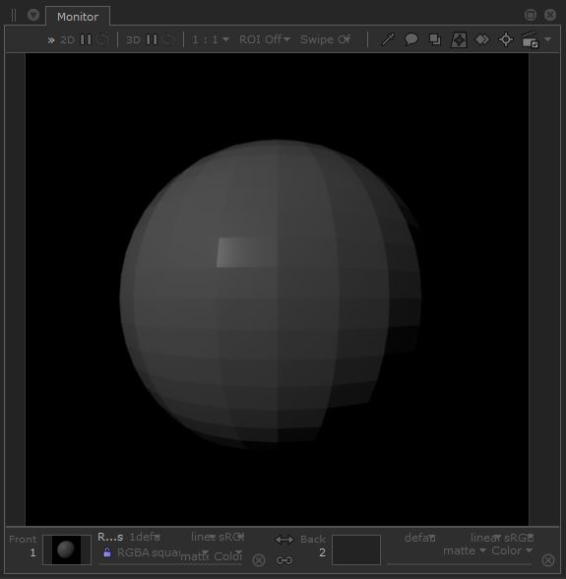
To perform a preview render of the scene created in this tutorial, right-click on the GafferThree node, and select Preview Renders. The scene generated at the GafferThree node is sent to the renderer. This uses your production renderer, not an internal Katana renderer (Katana does not have an internal renderer of its own).
You can view the progress of the render in the Render Log tab and the results are displayed in the Monitor tab (click the Monitor tab next to the Node Graph tab when using the default workspace to access the Monitor). To have the render fit the size of the Monitor tab, press F.
For more on rendering, saving your renders, and changing render settings, see Rendering Your Scene. For more on viewing the results of your renders, see Viewing Your Renders.
That’s it! You now know the basics on wielding Katana.
Sorry you didn't find this helpful
Why wasn't this helpful? (check all that apply)
Thanks for your feedback.
If you can't find what you're looking for or you have a workflow question, please try Foundry Support.
If you have any thoughts on how we can improve our learning content, please email the Documentation team using the button below.
Thanks for taking time to give us feedback.