Creating a Network Material
To create a network material:
| 1. | Create a NetworkMaterial node and add it to your recipe. |
Network materials are usually created in their own branch and a Merge node is used to connect them to the rest of the recipe.
| 2. | Select the NetworkMaterial node and press Alt+E. |
The NetworkMaterial node becomes editable within the Parameters tab.
| 3. | Enter the material’s name in the name parameter. |
Although it's not strictly needed, as Katana handles name clashes gracefully, it's good practice to name the network material, as the name is used for both the node name and the material’s scene graph location.
| 4. | In the namespace parameter, enter the location below /root/materials to place the material. |
By default, the material is placed below /root/materials in the scene graph, so you don't need to add this in the nameSpace field. Some of the most common namespaces are included as a dropdown to the right of the parameter. You can also specify nested namespaces, for instance, if the namespace parameter is geo/metals, the material is placed in the scene graph below /root/materials/geo/metals.
Adding Ports to a NetworkMaterial Node
On its own, a NetworkMaterial node only creates a scene graph location and it needs to have terminals/ports added to allow the connection of shading nodes. These ports are shader-specific and multiple ports can be added to the same NetworkMaterial node. To add ports, click Add Terminal and select a port type from the terminal type dropdown.
Connecting into a NetworkMaterial Node
A shading node is connected into a NetworkMaterial node’s input port. The type of shading node that connects is renderer specific, for instance the DlShadingNode node. Also, the shader that is assigned to the shading node needs to be of the correct type for the renderer and the NetworkMaterial node’s port.
For example, when creating a 3Delight surface shader as a network material, the shader node that connects to the NetworkMaterial node’s dlSurface port must be a valid surface shader (either of type surface or when using a class based shader, implement one of the expected methods for a surface shader).
Connection Logic Checking
Connections between shading nodes support connection checking logic, so when connecting shading nodes together through the UI, only permissible connections are allowed. For example:
| 1. | In an empty recipe, create two ArnoldShadingNodes. Set one to nodeType image, and the other to nodeType spot_light. |
| 2. | In the image type shading node, set the filename parameter to point to an image. |
| 3. | Click on the right output arrow of the image shading node to see the available outputs, which are r, g, b, and a. |
For this example, click on the r to select the red channel of the image shading node, then click on the left input arrow of the spot_light shading node.
| 4. | A new window shows the connection options. |
The input ports on the standard node that cannot accept an r input, such as decay_type, are grayed out.
Note: Holding the mouse over an output or input channel shows the type it generates or accepts. In the image above, you can see the r channel output of the image nodes provides a float.
| 5. | Connect the r channel output of the image shading node to the penumbra_angle input of the spot_light shading node, which accepts float, RGB, RGBA, vector, point, or point2 inputs. |
Note: To connect an output to an input, click on the output arrow of the source shading node, and click on the output you want. Then, click on the input arrow of the target shading node, and select the input you want to connect to.
Showing Connections
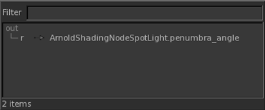
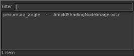
Once two shading nodes are connected, they’re joined in the Node Graph by an arrow. Right-clicking on the arrow near the source node shows the outputs from that node, and what they connect to on the target node. For example, open the recipe created in Connection Logic Checking. Right-click on the arrow connecting the image and spot_light ArnoldShadingNodes. When the mouse is closer to the image node, the following is displayed:

This indicates that the r output is connected to the penumbra_angle input of a node named, in this case ArnoldShadingNodeSpotLight. Right-clicking with the mouse closer to the spot_light shading node produces the following:

This indicates that the penumbra_angle input has an incoming connection from the r output of a node named, in this case ArnoldShadingNodeImage.
