Using a Network Shading Node
Shading nodes for network materials have a different appearance to other nodes. Inputs for the shading node are accessed by clicking the triangle on the left of the node and outputs by clicking the triangle on the right. The green square shows when this node is editable in the Parameters tab. It is not possible to view the scene graph generated at this node. To view how this node influences the scene graph you can view the scene graph generated at its NetworkMaterial node.
Creating a Shading Node
| 1. | Create a shading node and add it to the recipe. |
The renderer name acts as a prefix for the shading node. So for the 3Delight renderer, the shading node is called dlShadingNode, and for the Arnold renderer, the shading node is ArnoldShadingNode.
| 2. | Select the shading node and press Alt+E. |
The shading node becomes editable within the Parameters tab.
| 3. | From the nodeType dropdown, select the shader for this node. |
The parameters for the shader display in the parameters dropdown below nodeType.
Tip: A quick way to name the node from the nodeType is to middle-click and drag from the nodeType label to the name parameter.
Connecting a Shading Node
There are two main ways to connect shading nodes, you can:
| 1. | Click the output arrow |
A list of possible inputs displays. Again, this list depends on the shader.
| 2. | Select the output parameter from the list. |
This creates the output connection, highlighted in yellow, that follows your cursor until you click.
| 3. | Click the input arrow |
A list of possible inputs is displayed. The contents of the list depends on the shader.
| 4. | Select an input from the list. |
This creates the input connection.
Using this method, it's also possible to connect the nodes in reverse order by first selecting the input parameter of one shading node and then selecting the output parameter of another.
OR
| 1. | Hover the cursor over the first node you want to connect. |
| 2. | Press the Backtick key (‘) once. |
| 3. | Hover the cursor over the second node and press the Backtick key again. |
The first output from the first node is connected to the first input of the second.
Connection Logic Checking
Connections between shading nodes support connection checking logic, so when connecting shading nodes together through the UI, only permissible connections are allowed. For example:
| 1. | In an empty recipe, create two DlShadingNodes. Set one to nodeType file, and the other to nodeType spotLight. |
| 2. | In the file type shading node, set the image name parameter to point to an image. |
| 3. | Click on the right output arrow |
For this example, click on the outAlpha to select the alpha channel of the image shading node, then click on the left input arrow ![]() of the spotLight shading node.
of the spotLight shading node.
| 4. | A new window shows the connection options. |
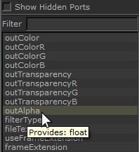
The input ports on the standard node that cannot accept an outAlpha input (such as Decay Rate) are grayed out.
Note: Holding the mouse over an output or input channel shows the type it generates or accepts.
In the image above, you can see the outAlpha channel output of the image nodes provides Float.
| 5. | Connect the outAlpha channel output of the image shading node to the PenumbraAngle input of the spotLight shading node, which accepts float inputs. |
Note: To connect an output to an input, click on the output arrow ![]() of the source shading node, and click on the output you want. Then, click on the input arrow
of the source shading node, and click on the output you want. Then, click on the input arrow ![]() of the target shading node, and select the input to which you want to connect.
of the target shading node, and select the input to which you want to connect.
Showing Connections
Once two shading nodes are connected, they’re joined in the node graph by an arrow. Left-clicking on the arrow near the source node shows the outputs from that node, and what they connect to on the target node.
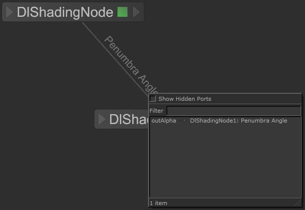
For example, open the recipe created in Connection Logic Checking and left-click on the arrow connecting the image and spotLight DlShadingNodes. When the mouse is closer to the image node, the following is displayed:

This indicates that the outAlpha output is connected to the Penumbru Angle input of a node named, in this case DlShadingNode1. Left-clicking with the mouse closer to the spotLight shading node produces the following:

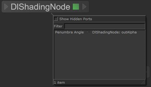
This indicates that the Penumbra Angle input has an incoming connection from the outAlpha output of the (in this case) DlShadingNode.
Disconnecting a Shading Node
To disconnect one shading node from another:
| 1. | Hover the mouse over the input connection and click when it turns yellow. |
A connection list displays.
| 2. | Select the link in the list. |
The link becomes disconnected.
| 3. | Click an empty area in the Node Graph tab. |
Exposing a Shading Node’s Parameters
Materials can be built from a large number of shading nodes, which might make it difficult to work out which parameters are important. Instead of trying to find the relevant parameters manually, you can flag shading node parameters as important by creating an interface of exposed parameters to be used when editing the material. To expose a shading node's parameters:
| 1. | Select the shading node and press Alt+E. |
The shading node becomes editable within the Parameters tab.
| 2. | Click the |
The Material Interface Options dialog displays.
| 3. | Enter the details for the public interface in the dialog: |
• In the Name field, enter the name for this parameter’s public interface.
• In the Group field, enter the name for a group that acts as a parent for this parameter’s public interface.
If only the Group field is populated, the parameter’s public interface becomes the actual parameter name (grouped under the contents of Group).
| 4. | Once you've set the details, click OK. |
The parameter is exposed in a ShadingNodeSubnet's Subnet Material Interface and a tag appears beneath the parameter in the shading node's Parameters tab, listing the details of the exposed parameter.
Note: For more on the Subnet Material Interface and the Material Public Interface, continue to Collecting Shading Nodes Inside a ShadingNodeSubnet and Creating a Network Material’s Public Interface.
Collecting Shading Nodes Inside a ShadingNodeSubnet
To help keep the shading network clear, it is possible to group shading nodes inside a node similar to a Group node, called a ShadingNodeSubnet. The main difference between a ShadingNodeSubnet node and a Group node is its ability to display and re-order the public interface (explained more in Creating a Network Material’s Public Interface) of the shading nodes within.
To add nodes to a ShadingNodeSubnet node:
| 1. | Create a ShadingNodeSubnet node. |
| 2. | Click the |
| 3. | Select the nodes to be added then Shift+middle-click and drag the nodes over the opened subnet’s group. When the subnet’s group highlights, release the mouse button. |
To add the shading node’s exposed parameters to the ShadingNodeSubnet’s Subnet Material Interface:
| 1. | Select the ShadingNodeSubnet node and press Alt+E. |
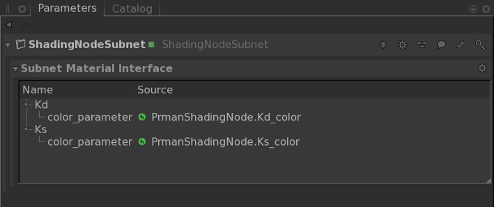
The ShadingNodeSubnet node becomes editable within the Parameters tab and the Subnet Material Interface displays. By default, this appears empty.
| 2. | Select the shading nodes with exposed parameters, and Shift+middle-click and drag the nodes into the Subnet Material Interface within the Parameters tab. |
The exposed parameters are shown in the Subnet Material Interface.

Note: If you attempt to drag any shading nodes into the Subnet Material Interface but they do not display, ensure that it has exposed parameters within it. If you have multiple nodes selected, and there is a node that does not have exposed parameters within it, the exposed parameters of all the selected nodes are still added to the interface.
These parameters can be re-ordered, setting a preference for how they should be displayed downstream. This preference can always be overriden by a NetworkMaterial node, and only acts as a default. To re-order the exposed parameters, middle-click and drag one group or parameter to another valid location. An orange line highlights the new position.
You can also modify the order of the exposed parameters for a NetworkMaterial node. Do this by dragging and dropping them in the Material Interface widget, in the base NetworkMaterial node.
