Rendering Instances
As a simple example, create two primitives under a single group location, make the group location the instance source, and instance the group to three instance locations:
| 1. | Create Primitives Under a Single Group Location, then Make that the Instance Source |
| 2. | Create Instance Locations that Reference the Instance Source |
| 3. | Add Bounds to the Instance Locations and Force Expand the Instance Source |
| 4. | Render the Scene to See the Instances |
Create Primitives Under a Single Group Location, then Make that the Instance Source
| 1. | Add two PrimitiveCreate nodes, and a Merge node to an empty recipe. |
Connect the output of each PrimitiveCreate node to an input on the Merge node.
| 2. | Set one PrimitiveCreate node's type parameter to cube, and the other to cone. Position the two primitives in the Viewer tab. |
| 3. | Change the name parameters of the PrimitiveCreate nodes to read /root/world/geo/instanceGroup/primitiveCube and /root/world/geo/instanceGroup/primitiveCone respectively. |
Note: Both primitives are grouped under a single group location, in this case named instanceGroup. You'll make this group location the instance source.
| 4. | Add an AttributeSet node, downstream of the Merge node. |
Specify the AttributeSet node to point to the instanceGroup group location in the scene graph.
| 5. | In the AttributeSet node, set the attributeName parameter to type, the attributeType to string, and the stringValue to instance source. |
Note: The scene graph location of the instance source is wrapped in a Katana procedural (• katana). This is a render agnostic workflow that will also work with Prman and Arnold.
The workflow associated with your preferred renderer may be more efficient. Check their documentation for details.
Create Instance Locations that Reference the Instance Source
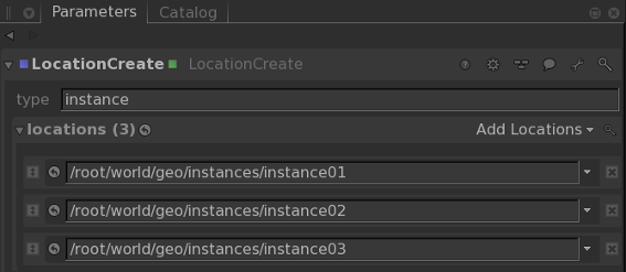
| 1. | In a separate branch in the recipe, add a LocationCreate node. Edit the type parameter of the LocationCreate node to read instance. |
| 2. | Choose Add Locations > path twice, to add two more locations, and edit the paths to read /root/world/geo/instances/instance01, /root/world/geo/instances/instance02, and /root/world/geo/instances/instance03. This creates three locations of type instance, under a single group location (named instances in this case). |
| 3. | Add a Transform3D node for each instance location, then move them away from the origin, and far enough from each other that the eventual instanced geometry does not overlap. |
| 4. | Point the instance locations to the instance source. |
Add an OpScript node, and set the CEL field to collect all instance locations by choosing Add Statements > Custom and entering - in this case - /root/world/geo/instances//*
Enter the following in the OpScript node's script parameter to set each instance location’s geometry.instanceSource attribute (in this case /root/world/geo/instanceGroup):
local source = "/root/world/geo/instanceGroup"
local attributeName = "geometry.instanceSource"
local attributeValue = StringAttribute(source)
Interface.SetAttr(attributeName, attributeValue)
Add Bounds to the Instance Locations and Force Expand the Instance Source
You have created an instance source location, and instance locations that reference that instance source. You need to make at render time that the instance source location is expanded before any of the instances, otherwise the geometry attributes required by the instances won't be present. To do this, add bounds to each of the instance locations to make sure those locations are expanded only as needed, and force expand the instance source location to make sure it is expanded first.
| 1. | Add an AttributeSet node downstream of the LocationCreate node that creates the instances. Point the node at the instance locations. |
| 2. | Set the AttributeSet node's attributeName parameter to bound, the attributeType to double, and the number value to a 6 X 1 array. Enter values for the bounds that you're certain encompass all of the (to be) instanced geometry. The bounds do not have to be accurate, and can be very large. |
Note: Bounds are set using a 6 X 1 array, specifying the minimum and maximum extents of the bounding box in each of the X, Y, and Z axis. The convention is [ mix x, max x, min y, max y, min z, max z ]
| 3. | Add an AttributeSet node downstream of the two PrimitiveCreate nodes, and point it to the instance source location. |
Set the attributeName parameter to forceExpand, the attributeType to integer, and the numberValue to 1.0.
Render the Scene to See the Instances
Add a camera to your scene, so you can render, and see the instance source location instanced at each of the instance locations.
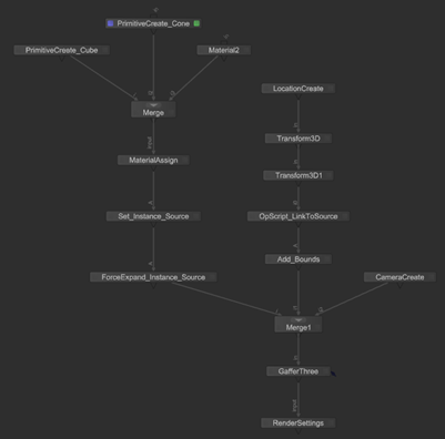
| 1. | Add a CameraCreate node, and another Merge node, and connect the outputs of the CameraCreate node, instances branch, and instance source branch, to inputs on the Merge node. Your Node Graph should display similar to that shown below. |
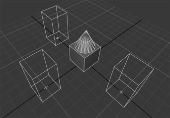
| 2. | Position the camera to frame all of your instance locations in the viewer. You'll see the geometry under the instance source location, and the instance locations (represented by their bounding boxes and locators). |
| 3. | Right-click on the final Merge node and choose Preview Render. You'll see that the geometry under the instance source location is rendered, along with instances of the same geometry at each of the instance locations. |
Experiment: Create two materials and assign them to the geometry locations under the instance source location. Add a GafferThree node, and lights, then Preview Render your scene again.