Search is based on keyword.
Ex: "Procedures"
Do not search with natural language
Ex: "How do I write a new procedure?"
BRDF (Shader Network) Node
Access: Nodes > Shader Network > BRDF
The BRDF node and its inputs.
The BRDF Node is realistic shading model with recreates the way light reflects at different angles, providing Fresnel effects.
A shader node is a way to view multiple texture maps at once. You can view what they affect at render time, rather than as a single color map on your mesh. They are a great way to texture and Lookdev on the fly and make sure you textures have the correct values.
The Shader Network version of the node includes a few extra properties that have been set up inside the node’s group. These are the Bump, Vector and Displacement inputs which can be added to the shader.
Tip: Press Ctrl+double click on the node to jump into the group and see the construction of the aspects of the node.
BRDF (Shader Network) Node Inputs
| Input | Description |
| Diffuse Color | Assigns the input texture to the Diffuse Color of the shader. |
| Specular Color | Assigns the input texture to the Specular Color of the shader. |
| Glossiness | Assigns the input texture to the Glossiness value of the shader. |
| Reflectance | Assigns the inputted texture to the Reflectance value of the shader. |
| Ambient Occlusion | Assigns the input texture to the Ambient Occlusion value of the shader. |
| Emissive Color | Assigns the input texture to the Emissive Color of the shader. |
| Normal | Assigns the input texture to the Normal Map of the shader. |
| Bump | Assigns the input texture to the Bump Map of the shader. |
| Vector | Assigns the input flow map to the Vector Map of the shader. See Vector Brush for more information. |
| Displacement | Assigns the input texture to the Displacement value of the shader. |
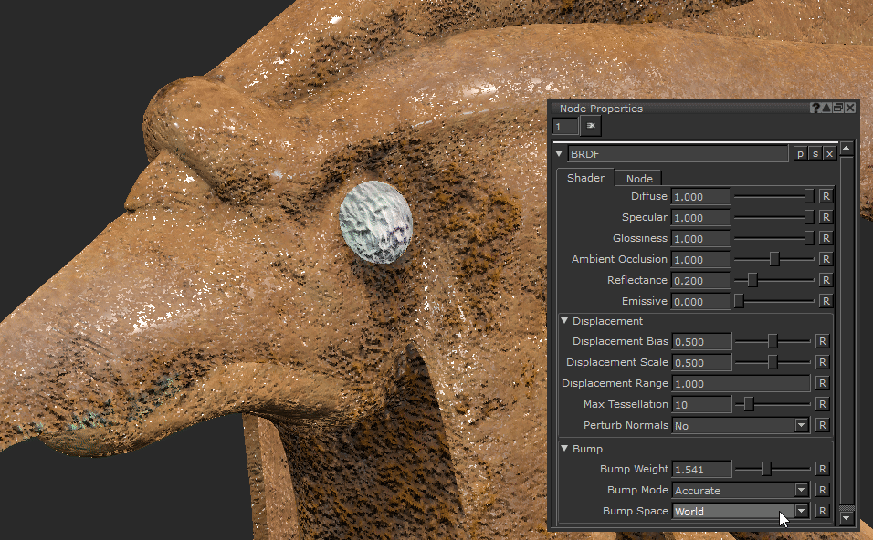
BRDF (Shader Network) Node Properties
The images in the examples here are using a fully texture asset with channels plugged into the associated inputs of the shader and an environment light for reflections..
|
Diffuse Text field, slider |
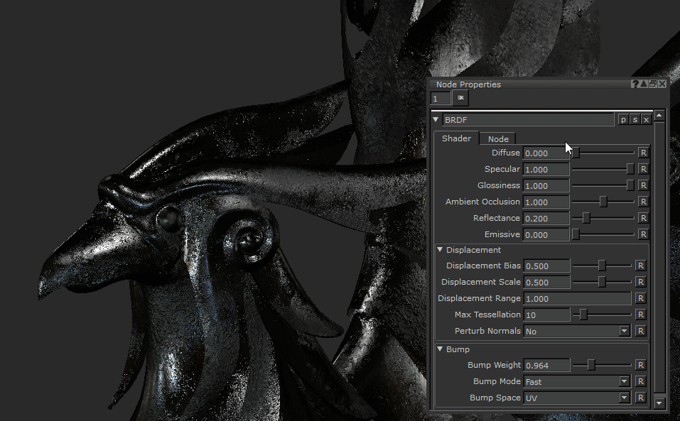
A multiplier of your connected Diffuse Color input. Lowering this to 0 will give you a black diffuse.
Default is 1. |
||||
|
Specular Text field, slider |
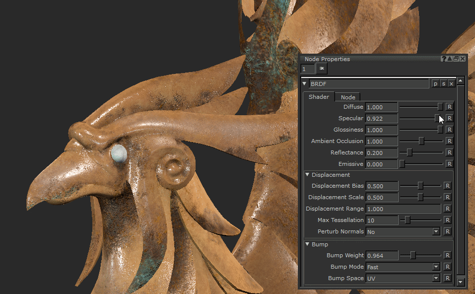
A multiplier of your connected Specular Color input. Lowering this to 0 will give you a black specular value.
Default is 1. |
||||
|
Glossiness Text field, slider |
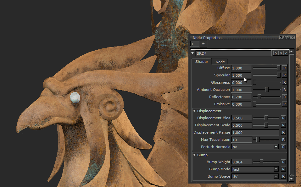
Changes the tightness of the specular highlights and reflections. A value of 1 will give you very glossy highlights, and 0 will give a much rougher broad specular.
Default is 0.2. |
||||
|
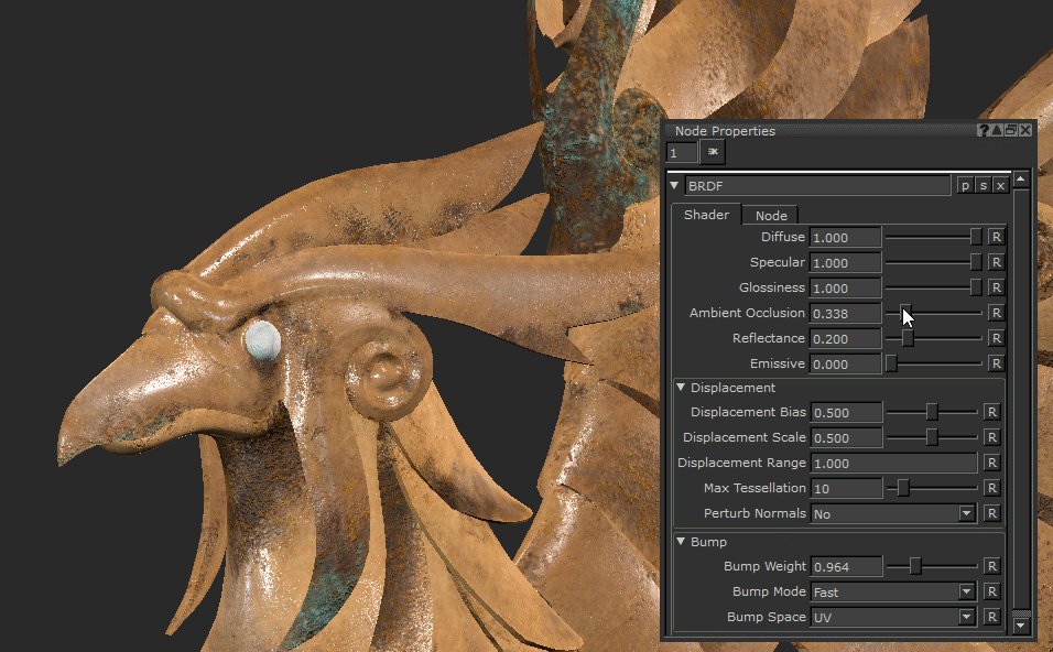
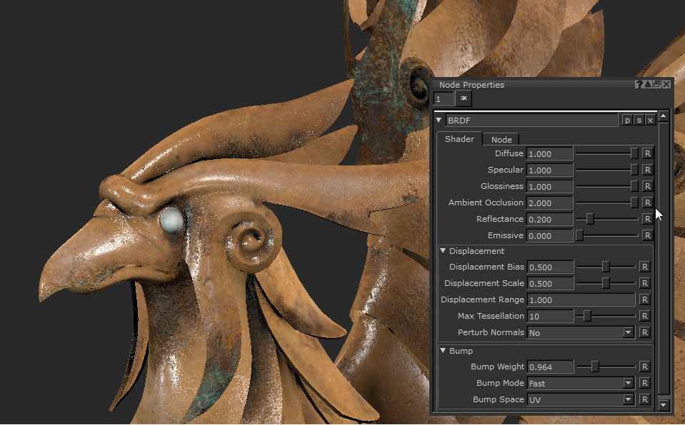
Ambient Occlusion Text field, slider |
A multiplier which raises and lowers the effect of Ambient Occlusion on your model. Requires Ambient Occlusion to be calculated from the Object Menu to have any affect - (Object > Ambient Occlusion)
Default is 1. |
||||
|
Reflectance Text field, slider |
Raises and lowers the reflected light off the surface. This property along with Specular Colour and Glossiness will affect how specular highlights and reflections are displaced on your object.
Default is 0.2. |
||||
|
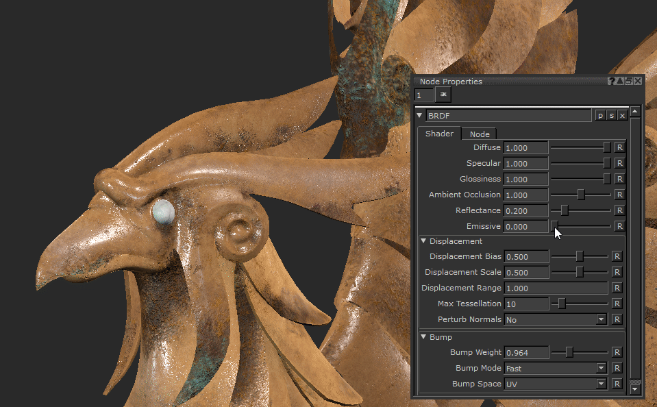
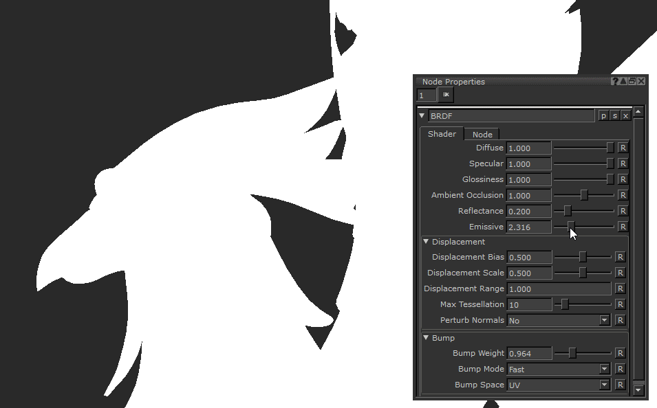
Emissive Text field, slider |
A multiplier to the input Emissive Color. Requires an input to have affect.
Default is 1. |


Displacement
Note: Displacement in Mari can cause a strain on your machine, especially in heavy scenes.
|
Displacement Bias Text field, slider |
Changes the midpoint of the displacement, and what value will not displace. 0.5 means mid gray will have no change, 1.0 will push out, 0.0 will push in. Default is 0.5. |
|
Displacement Scale Text field, slider |
Changes the intensity of the displacement of the geometry. Default is 0.5. |
|
Displacement Range Text field |
Sets the range for the search distance. Default is 1.000. |
|
Max Tessellation Text field, slider |
Raising this will increase the fidelity of the displacement being displayed. This will increase the look and accuracy of the displacement but decrease performance. Default is 10. |
|
Perturb Normals dropdown |
If Yes is selected the normals will remain as they were when not-displaced after the geometry is moved. Default is No. |
Bump
|
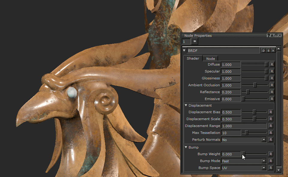
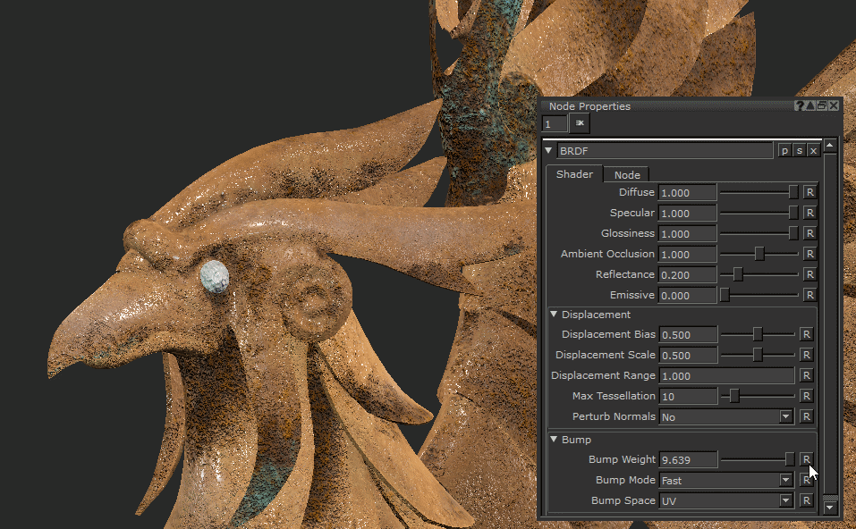
Bump Weight Text field, slider |
Changes the strength of the Bump being applied to the geo’s surface.
Default is 0.1. |
||||||
|
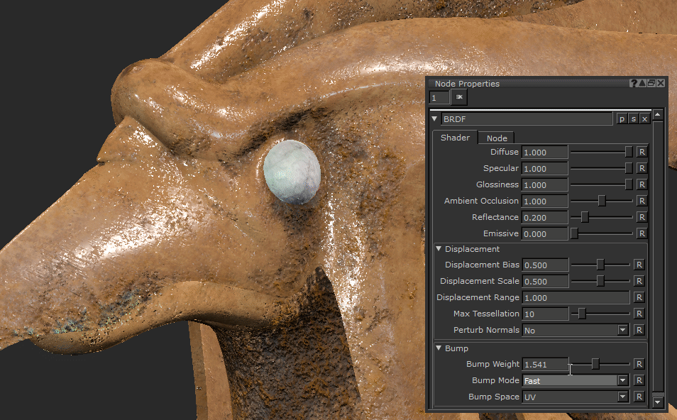
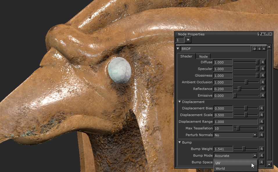
Bump Mode dropdown |
Defines the calculation method of the bump being displayed. You can change it between Fast, Accurate or Fastest. Accurate will give you the smoothest calculation method but will take longer to calculate which can slow down your scene and shader. Fastest is the quickest to calculate but you can get odd results and anomalies on a per pixel basis giving you an inaccurate result.
Default is Fast. |
||||||
|
Bump Space dropdown |
Changes the calculation of the normals for the Bump map between UV and World coordinate space. • UV - Normals are calculated relative to the UV coordinates space. The UV Bump Space mode is the more traditional approach but can lead to noticeable seams and color variations. • World - Normals are calculated relative to the World coordinates space. Using the World Bump Space mode gives a more seamless result.
Default is UV. |


BRDF (Shader Network) Node Workflow
Shaders are an important aspect of material creation in Mari. Regardless of which shading model you use, being able to view multiple channels at once is the best way to view your textures as you have an accurate representation of how they will behave at render time. This is important in any situation, whether it’s working on your own work at home or in a big studio where your textures will go to the lookdev department to be rendered.
Having the knowledge of seeing what you plug into your shaders is important and will save you time tweaking and editing them in the renderer.
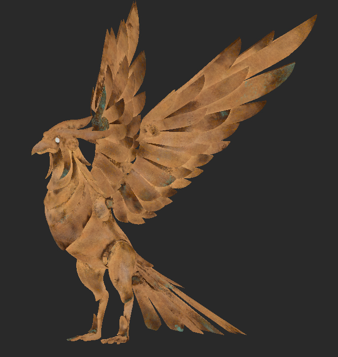
Here’s the Color map for a mechanical bird asset.
Viewing a texture map as a flat color on your geometry is important, but also inputting it into a shader to view the shaded versions of maps like Bump, Roughness, and Normal helps you see where your textures are or aren’t working.
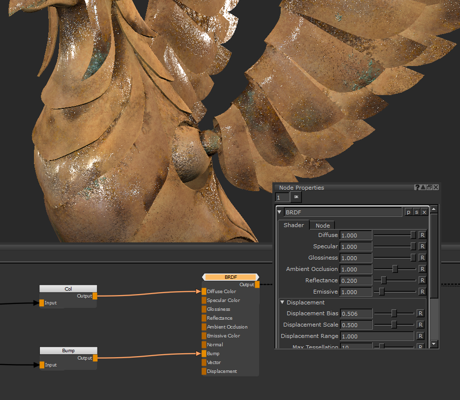
To set up a shader, connect a Base Color. Drag and drop a connection from your color channel to the Diffuse Color input. By doing this you are telling the shader what the value of the base color is.
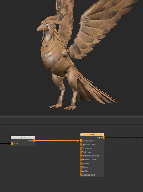
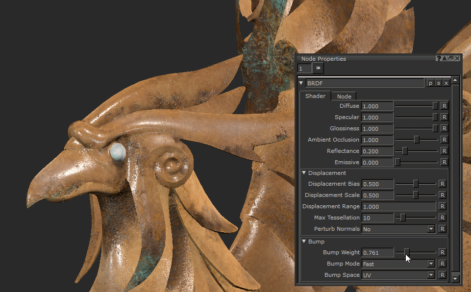
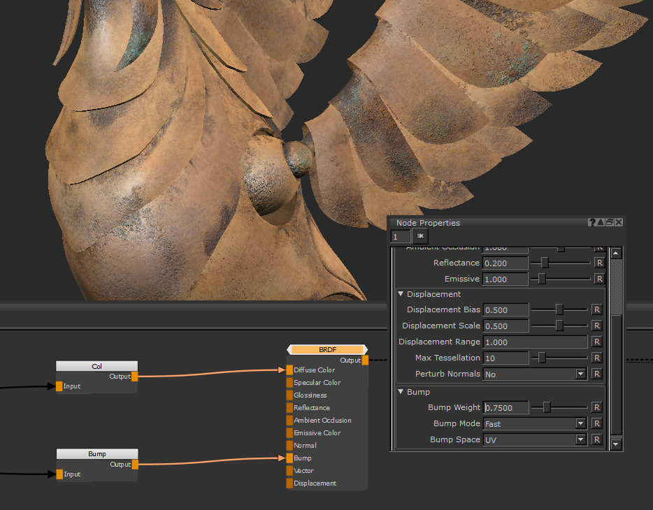
We can now start to visualize the object with specular and shadows rather than just flat color. From there, you can start plugging in other channels you have textured into your shader, such as a bump map into the Bump input.

It’s not made much of a difference on the Bump Weight base setting of 0.1, so we can increase that to 0.75 to see the result a bit more clearly.
But what if you don’t have a map to input? We haven’t yet painted a gloss map for the Glossiness input of the shader, but by using the slider on the shader you can find a rough value that works well to get you the results you like. First though, make sure to turn glossiness up to 1.0. That way the value we plug in will not be multiplied so we know we are seeing it correctly.
We can use a Constant node plugged into Glossiness. This is just a value between 0 and 1 that we can use to find a value to start painting our roughness map with.
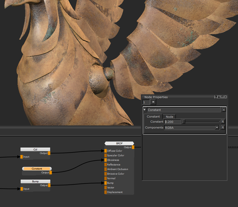
This value of 0.2 works well for a broader glossiness value on the rusty areas.
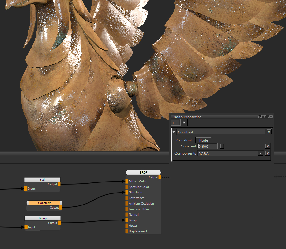
And this tighter specular Glossiness value of 0.6 looks good on the smoother areas for a less damaged metal effect.
We now have two values of 0.2 and 0.6 to use in our Glossiness map. This is now a value to aim for, you can make sure whatever you end up inputting is roughly around that level. This is a great way that a shader can be used to help you texture and lookdev at the same time.
Related Nodes
Sorry you didn't find this helpful
Why wasn't this helpful? (check all that apply)
Thanks for your feedback.
If you can't find what you're looking for or you have a workflow question, please try Foundry Support.
If you have any thoughts on how we can improve our learning content, please email the Documentation team using the button below.
Thanks for taking time to give us feedback.