Custom Shader API
Introduction
Mari renders a scene in the canvas using its extensible shader system based on a node graph. Shaders and layers in Mari are in the form of nodes internally. Custom shaders and layers can be added to Mari easily. This is done by supplying to Mari XML files defining custom shaders and layers in the form of nodes. Once a node definition XML file is written, the node can be registered to Mari using either Python API or a text file. Mari carries a shader development console to aid the development of custom shaders and layers.
Quick Start
This section explains steps to register a custom adjustment layer that posterizes the result.
Create a file ~/Posterize.xml (On Windows, C:\Users\USERNAME\Posterize.xml) with the following XML pasted in:
<Node>
    <ID>MY_EXAMPLE_Posterize_Adjustment</ID>
    <Tags>
        <Tag>_adjustment</Tag>
    </Tags>
    <Inputs>
        <Input Name="Input"></Input>
    </Inputs>
    <Attributes>
        <Attribute Name="Colors" Description="The number of colors after posterization" Group="" Type="double" Min="0.0" Max="256" Logarithmic="true">8</Attribute>
    </Attributes>
    <Contexts>
        <Context Type="GLSL">
        <Shader>
            <Inputs>
            <Input Name="Input"><Default>vec4(1,1,1,1)</Default></Input>
            </Inputs>
            <Body>
            <![CDATA[
        Output.rgb = round($Colors * #Input.rgb) / $Colors;
        Output.a = #Input.a;
            ]]>
            </Body>
        </Shader>
        </Context>
    </Contexts>
</Node>
Linux: Create a file ~/Mari/Scripts/register_custom_layers.py with the following python code pasted in:
mari.gl_render.registerCustomAdjustmentLayerFromXMLFile("Posterize","~/Posterize.xml")Note
Mari by default reads any custom .py files from ~/Mari/Scripts directory.
Windows: Create a file C:\Users\USERNAME\Documents\Mari\Scripts\register_custom_layers.py with the following python code pasted in:
mari.gl_render.registerCustomAdjustmentLayerFromXMLFile("Posterize","C:\Users\USERNAME\Posterize.xml")Note
Mari by default reads any custom .py files from C:\Users\USERNAME\Documents\Mari\Scripts on Windows.
Launch Mari
Open a project
In the “Layers” palette, create a new “Posterize” layer.
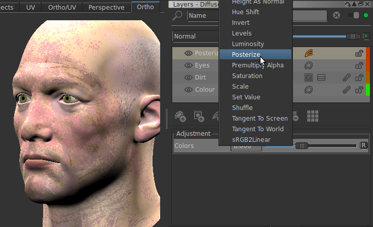
Node/Layer Examples
Specular Example
This example specular component shader does Phong specular calculation. Save this XML in a file and register it with a python command like:
mari.gl_render.registerCustomSpecularShaderFromXMLFile("My Phong","/The/path/to/the/file")
<Node>
    <ID>MY_EXAMPLE_Phong_Specular</ID>
    <Inputs>
        <Input Name="SpecularColor" PrettyName="Specular Color" PreferredInput='1'></Input>
        <Input Name="SpecularShininess" PrettyName="Specular Shininess"></Input>
        <Input Name="Normal"></Input>
    </Inputs>
    <Attributes>
        <Attribute Name="SpecularShininess" PrettyName="Specular Shininess" Group="" Type="double" Min="0" Max="100">10</Attribute>
    </Attributes>
    <Tags>
        <Tag>_notcacheable</Tag>
        <Tag>_specular</Tag>
    </Tags>
    <Contexts>
        <Context Type="GLSL">
        <Shader ShaderType='Fragment'>
            <Inputs>
            <Input Name="SpecularColor"><Default>vec4(1,1,1,1)</Default></Input>
            <Input Name="SpecularShininess"><Default>vec4(1,1,1,1)</Default></Input>
            <Input Name="Normal"><Default>vec4(0,0,1,1)</Default></Input>
            </Inputs>
            <Body>
            <![CDATA[
        vec3 E = normalize(-State.ViewVectorInEyeSpaceFromViewCamera);
        vec3 N = normalize(#Normal.xyz);

        float Shininess = $SpecularShininess*#SpecularShininess.r;

        vec3 Specular = vec3(0.0);

        for(int i = 0; i < 4; i++)
        {
            //Light Direction
            vec3 L = normalize(u_MriLightSources[i].Position.xyz - State.FragmentPositionInEyeSpaceFromViewCamera);
            //Reflection Vector
            vec3 R = 2.0*dot(L,N)*N - L;

            float LightVisibility = mriLightVisibility( i, State.Position);

            float NdotH = clamp( dot(R,E), 0.001, 0.999);

            // Phong specular
            Specular += pow(NdotH,Shininess) * u_MriLightSources[i].SpecularColor.rgb * LightVisibility;
        }

        Output.rgb = Specular * #SpecularColor.rgb;
        Output.a = #SpecularColor.a;
            ]]>
            </Body>
        </Shader>
        </Context>
    </Contexts>
</Node>
Warning
Deprecation: While still supported in legacy scenes, separate Specular and Diffuse shader types are considered deprecated and will be removed in a future version of Mari.
Diffuse Example
This example diffuse component shader does Lambertian diffuse calculation. Save this XML in a file and register it with a python command like :
mari.gl_render.registerCustomDiffuseShaderFromXMLFile("My Lambertian","/The/path/to/the/file")
<Node>
    <ID>MY_EXAMPLE_Lambertian_Diffuse</ID>
    <Inputs>
        <Input Name="DiffuseColor" PrettyName="Diffuse Color" PreferredInput='1'></Input>
        <Input Name="Normal"></Input>
    </Inputs>
    <Attributes>
    </Attributes>
    <Tags>
        <Tag>_notcacheable</Tag>
        <Tag>_diffuse</Tag>
    </Tags>
    <Contexts>
        <Context Type="GLSL">
        <Shader ShaderType='Fragment'>
            <Inputs>
            <Input Name="DiffuseColor"><Default>vec4(0,0,0,0)</Default></Input>
            <Input Name="Normal"><Default>vec4(0,0,1,1)</Default></Input>
            </Inputs>
            <Body>
            <![CDATA[
        vec3 N = #Normal.xyz;

        vec3 Diffuse = vec3(0.0);

        for(int i = 0; i < 4; i++)
        {
            //Light Direction
            vec3 L = normalize(u_MriLightSources[i].Position.xyz - State.FragmentPositionInEyeSpaceFromViewCamera);
            float LdotN = max(dot(L,N),0.0);

            float LightVisibility = mriLightVisibility( i, State.Position);

            // Lambertian Diffuse
            Diffuse += LdotN * u_MriLightSources[i].DiffuseColor.rgb * LightVisibility;
        }

        Output.rgb = Diffuse * #DiffuseColor.rgb;
        Output.a = #DiffuseColor.a;
            ]]>
            </Body>
        </Shader>
        </Context>
    </Contexts>
</Node>
Warning
Deprecation: While still supported in legacy scenes, separate Specular and Diffuse shader types are considered deprecated and will be removed in a future version of Mari.
Standalone Shader Example
This example standalone shader does combined Phong specular and Lambertian diffuse calculation. Save this XML in a file and register it with a python command like :
mari.gl_render.registerCustomStandaloneShaderFromXMLFile("My Phong and Lambertian","/The/path/to/the/file")
<Node>
    <ID>MY_EXAMPLE_Phong_Specular_And_Lambertian_Diffuse</ID>
    <Inputs>
        <Input Name="DiffuseColor" PrettyName="Diffuse Color"  ShortName="Diff" Scalar="False" PreferredInput='1'></Input>
        <Input Name="SpecularColor" PrettyName="Specular Color" ShortName="Spec" Scalar="False"></Input>
        <Input Name="SpecularShininess" PrettyName="Specular Shininess" ShortName="Shin" Scalar="False" ></Input>
    </Inputs>
    <Attributes>
        <Attribute Name="SpecularShininess" PrettyName="Specular Shininess" Group="" Type="double" Min="0" Max="100">10</Attribute>
    </Attributes>
    <Tags>
        <Tag>_notcacheable</Tag>
        <Tag>_standalone</Tag>
    </Tags>
    <Contexts>
        <Context Type="GLSL">
        <Shader ShaderType='Fragment'>
            <Inputs>
            <Input Name="DiffuseColor"><Default>vec4(0,0,0,0)</Default></Input>
            <Input Name="SpecularColor"><Default>vec4(1,1,1,1)</Default></Input>
            <Input Name="SpecularShininess"><Default>vec4(1,1,1,1)</Default></Input>
            </Inputs>
            <Body>
            <![CDATA[
        vec3 E = normalize(-State.ViewVectorInEyeSpaceFromViewCamera);
        vec3 N = State.NormalInEyeSpaceFromViewCamera;

        float Shininess = $SpecularShininess*#SpecularShininess.r;

        vec3 Specular = vec3(0.0);
        vec3 Diffuse = vec3(0.0);

        for(int i = 0; i < 4; i++)
        {
            //Light Direction
            vec3 L = normalize(u_MriLightSources[i].Position.xyz - State.FragmentPositionInEyeSpaceFromViewCamera);
            //Reflection Vector
            vec3 R = 2.0*dot(L,N)*N - L;

            float LightVisibility = mriLightVisibility( i, State.Position);

            float NdotH = clamp( dot(R,E), 0.001, 0.999);
            float LdotN = max(dot(L,N),0.0);

            // Phong specular
            Specular += pow(NdotH,Shininess) * u_MriLightSources[i].SpecularColor.rgb * LightVisibility;

            // Lambertian Diffuse
            Diffuse += LdotN * u_MriLightSources[i].DiffuseColor.rgb * LightVisibility;
        }

        Output.rgb = Specular * #SpecularColor.rgb + Diffuse * #DiffuseColor.rgb;
        Output.a = #DiffuseColor.a;
            ]]>
            </Body>
        </Shader>
        </Context>
    </Contexts>
</Node>
Procedural Layer Example
This example procedural layer generates a gradient in UV coordinate. Save this XML in a file and register it with a python command like :
mari.gl_render.registerCustomProceduralLayerFromXMLFile("My UV Gradient","/The/path/to/the/file")
Adjustment Layer Example
This example adjustment layer adjusts layers below by contrasting them. Save this XML in a file and register it with a python command like :
mari.gl_render.registerCustomAdjustmentLayerFromXMLFile("My Contrast","/The/path/to/the/file")
<Node>
    <ID>MY_EXAMPLE_Contrast_Adjustment</ID>
    <Tags>
        <Tag>_adjustment</Tag>
    </Tags>
    <Inputs>
        <Input Name="Input"></Input>
    </Inputs>
    <Attributes>
        <Attribute Name="Contrast" Group="" Type="double" Min="0.0" Max="10.0">1.0</Attribute>
        <Attribute Name="ContrastPivot" PrettyName="Contrast Pivot" Group="" Type="double" Min="0.0" Max="1.0">0.5</Attribute>
    </Attributes>
    <Contexts>
        <Context Type="GLSL">
        <Shader>
        <Inputs>
            <Input Name="Input"><Default>vec4(1,1,1,1)</Default></Input>
        </Inputs>
            <Body>
            <![CDATA[
        Output.rgb = (#Input.rgb-vec3($ContrastPivot))*$Contrast+vec3($ContrastPivot);
        Output.a = #Input.a;
            ]]>
            </Body>
        </Shader>
        </Context>
    </Contexts>
</Node>
Node graph Node Example
This example shows how to register a custom node in the node graph. Save this XML in a file and register it with a python command like :
mari.gl_render.registerCustomNodeFromXMLFile("My Color","/The/path/to/the/file")
<Node>
    <ID>MY_EXAMPLE_Color</ID>
    <DefaultName>My Color</DefaultName>
    <Attributes>
        <Attribute Name="Color" Group="" Type="color" >(1.0,1.0,1.0,1)</Attribute>
    </Attributes>
    <Contexts>
        <Context Type="GLSL">
        <Shader>
            <Body>
            <![CDATA[
        Output = $Color;
            ]]>
            </Body>
        </Shader>
        </Context>
    </Contexts>
</Node>
Other Examples
Examples of custom shader and layer XML definition files are supplied in [Mari installation directory]/Media/Examples/Nodes.
Examples of python files to register custom shader and layer registration Python supplied in [Mari installation directory]/Media/Scripts/mari/examples. See custom_shader.py and custom_layer.py.
Custom Shader and Layer Development Workflow
Workflow
Custom layers and shaders are developed in the following workflow. Initially, start creating your own node by the steps below:
Write a node XML file
Register the XML file as a layer or shader in Python API
Instantiate the layer or shader
Check the result
Then, iterate the steps below until the desired result is achieved:
Open the Shader Console from “Tools > Shader Console”
Check if there is any GLSL error
Modify your XML file to fix GLSL or improve the logic
Save the XML file
Hit “All” button in the Shader Console to apply the update to your XML file
Check the result
The “All” button enforces that Mari reloads the XML files, updates all layer and shader instances and recompiles GLSL shaders so that the update to the XML file is reflected in the scene.
Note
In Mari 1.X, shader development used to require restarting Mari the iterative development. In 2.X, shaders and layers can be developed using the Shader Console without restarting Mari.
Write an XML File
This section explains the essence of writing a node XML definition file. Refer to Node XML Reference for the list of elements Mari supports.
Basics
Mari’s layer and shader system is built on top of its node graph based processing engine, so every layer and shader is implemented as nodes. Writing a custom shader or layer is to write a node definition XML file that fulfills particular requirements for those types.
Inputs
Inputs of a node are input points to which preceding nodes supply their outputs.
Attributes
Attributes of a node are parameters of the node that can be adjusted in the GUI.
Tags
Tags of a node are the ways to tag the node so that the application or scripts can treat nodes that have specific tags in a special ways.
Contexts
Contexts of a node are sections to store information of the node specific to a particular context. Currently there is only GLSL context where GLSL code for the node is defined
Note
Mari saves each node information including GLSL code into the node instance so that Mari can replay the scene even if the original custom node XML files are missing. In other words, project archives carry the custom GLSL code and some other node information. If any sensitive code is implemented in the custom node XML files, please reconsider sharing the archive.
Custom Layer and Shader Types
There are 2 types of layers and 3 types shaders that can be registered with Mari’s shader system. Each type has some requirements on tags and the minimum number of inputs to be defined in the XML files.
Type |
Compulsory Tags |
Inputs |
Description |
|---|---|---|---|
Adjustment Layer |
_adjustment |
1 or more |
An Adjustment Layer adjusts the result of layer stack below the layer and blends the adjusted result with unmodified result through a layer mask. |
Procedural Layer |
0 or more |
A Procedural Layer generates some result procedurally or based on input images and blends the result with the result of layer stack below the layer through a layer mask . |
|
Diffuse Shader |
_diffuse |
1 or more |
A Diffuse Shader calculates the diffuse component of the lighting. The result is combined with specular component and forms the final lighting result. |
Specular Shader |
_specular |
0 or more |
A Specular Shader calculates the specular component of the specular. The result is combined with diffuse component and forms the final lighting result. |
Standalone Shader |
_standalone |
0 or more |
A Standalone Shader does its own calculation to interpret the supplied inputs. For example, it can do its own optimised diffuse, specular and other lighting effect calculation all together and outputs the result. Also, it does not have to do lighting but do some input validation. |
Warning
Deprecation: While still supported in legacy scenes, separate Specular and Diffuse shader types are considered deprecated and will be removed in a future version of Mari.
Shader Model Generation
Shader models are an abstraction that represents the inputs associated with a given shader and the properties of those inputs. Shader models are used by Mari when creating multi-channel layers and their associated nodes in order to generate the appropriate input/output streams and drive various user interfaces to match the requested shader. Shader models are generated automatically by Mari when it parses the xml for a shader node during application startup.
Note that shader models will only be generated for standalone lighting nodes, which are indicated by the presence of the “_standalone” tag.
Mari generates the shader model by inspecting the input list at the beginning of the node xml. Mari 4.5 introduces two additional properties for shader inputs. These are “ShortName” and “Scalar”.
Short names are abbreviated versions of the full input names which are used when UI space is limited. e.g. when displaying node input names in the node graph view. A valid shortname should be 4 characters long. If no shortname is provided, one will be automatically generated by Mari. Shortnames are sanitized according to the following rules:
If a pretty name is present, that will be used as the basis of the automatically generated shortname. Otherwise, the input name itself will be used as the basis.
The starting name will be truncated to four characters.
The abbreviated name will be made unique by dropping one or two letters from the end and replacing them with an incremental number from 2-99 as required. Note that there is no 0 or 1 index accounted for. For example, an input named “diffuse”, with a pretty name of “Diffuse” would be abbreviated as follows e.g. Diff, Dif2, Dif3 … Di99.
The scalar property indicates whether an input represents RGB data for calculations (etc specularity or bump)scalar, as opposed to color-managed RGB data. This is not currently used internally, but can be queried via the python API.
The list of registered shader models can be queried via the ShaderModelManager e.g.
...
import mari
shadermodels = mari.shader_models.list()
...
Individual inputs can be queried by name from a ShaderModel object. e.g.
...
firstInputName = myShaderModel.inputNames()[0] # gets the name of the first input in the shader model
firstInput = myShaderModel.input(firstInputName) # gets the first input as a ShaderModelInput object.
...
The properties of individual inputs are accessed via the ShaderModelInput object. e.g.
...
name = myInput.name();
prettyName = myInput.prettyName()
isScalar = myInput.scalar()
shortName = myInput.shortName()
...
Develop GLSL code
This section explains how to develop a GLSL code in a node XML file.
GLSL code for a custom node is to be written into the <Shader>’s <Body> element as text element. It is recommended to use CDATA in <Body> element because CDATA allows GLSL code without escaping special characters for XML. The code will be injected into a larger shader function by Mari, so it should be written as a nested code snippet. No functions should be defined within the snippet. If it is required to have a separate function, refer to Custom GLSL Header and Code.
Mari’s OpenGL support is primarily for OpenGL 3.2 onwards. Therefore, it’s best to write a GLSL code that conforms at least to OpenGL 3.2 and GLSL 1.5 specification. If displacement is needed the code needs to be written for OpenGL/GLSL 4.0+.
Inputs and the predefined “Output” variable are all vec4.
Mari adds special handling of inputs, output and attributes of the Node in extension to the standard GLSL code. Attributes and inputs can be accessed by putting the attribute and input names with prefixes ‘$’ and ‘#’ respectively.
Attributes of the node can be accessed within the code by prefixing the name of the attribute with ‘$’. For example
$MyAttributeInputs of the node can be accessed within the code by prefixing the name of the input with ‘#’. For example
#MyInputOutput of the node is predefined as
vec4 Output. The result of the node needs to be written into this.
For example, the code like below will multiply MyInput by MyAttribute and outputs the result as the result of the node.
...
<Body>
<![CDATA[
    Output = vec4($MyAttribute) * #MyInput;
]]>
</Body>
...
Refer to GLSL Reference for the list of globally available functions and uniforms.
Refer to Node Attribute Types for the list of attribute types.
Shader Console
The “Shader Console” is a convenient tool to develop the GLSL code for a custom shader and layer. Go to “Tools > Shader Console” in the main window to open the “Shader Console”.
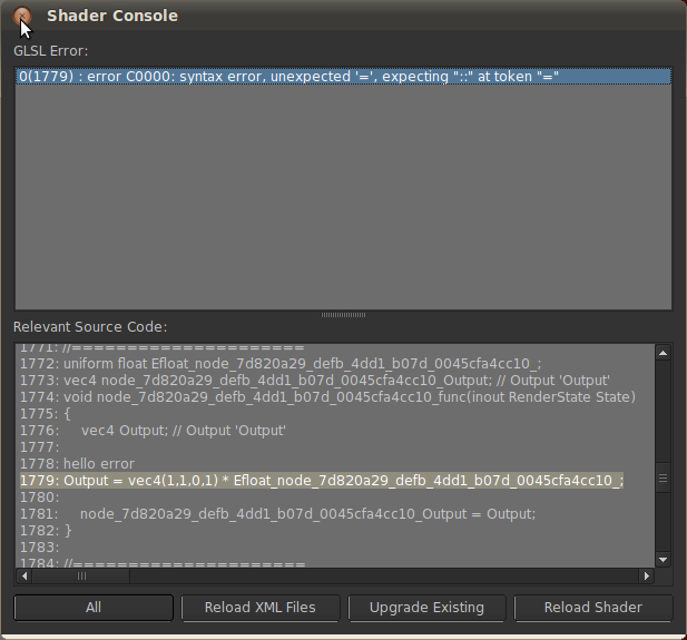
When the compilation of GLSL code fails, the error and source code listing views show the error and relevant source code.
Roles of the buttons are described below:
All
“All” button forces Mari to reload the node definition XML files, update the existing shaders and layers and reloads shaders.
Reload XML Files
“Reload XML Files” button forces Mari to reload the node definition XML files. This will not update the existing shader or layers.
Upgrade Existing
“Upgrade Existing” button forces Mari to update existing shaders and layers with up-to-date XML definitions This also forces the shader to reload relevant shaders.
Reload Shader
“Reload Shader” button forces Mari to reload shaders without upgrading existing shaders or layers.
Note
The GLSL code for a custom shader or layer is not compiled or linked until the shader or layer is instantiated and used to render the scene in the canvas. Mari optimises the generated code, so any nodes that are within hidden or cached layers are also not included for shader compilation or linking. In other words, the custom shader or layer needs to be used actively for rendering of the canvas
Note
Some of Mari’s internal shader code is proprietary and encrypted. These encrypted sections of the shader code are displayed as asterisks in the Shader Log and Mari Log.
GLSL Shader Types
OpenGL supports different types of shaders such as fragment shaders, tessellation evaluation shaders etc. Different GLSL code or input default values can be defined for different types of shaders.
Mari’s shader and layer system currently supports two shader types. The layers fed into Displacement input of a shader will be evaluated in the tessellation evaluation shader. The rest are evaluated in the fragment shader.
Write multiple <Shader> elements with ShaderType attribute specifying the shader type. If no ShaderType is supplied, that is used for all shader types that do not have definitions. See the example below.
...
<Context Type="GLSL">
    <Shader>
        <Inputs>
        <Input Name="Input"><Default>vec4(1,1,1,1)</Default></Input>
        </Inputs>
        <Body>
        <![CDATA[
        Output.rgb = #Input.rgb;
        Output.a = #Input.a;
        ]]>
        </Body>
    </Shader>
    <Shader ShaderType="TessEvaluation">
        <Inputs>
        <Input Name="Input"><Default>vec4(0.5,0.5,0.5,1)</Default></Input>
        </Inputs>
        <Body>
        <![CDATA[
        Output.rgb = #Input.rgb * vec3(2.0);
        Output.a = #Input.a;
        ]]>
        </Body>
    </Shader>
</Context>
...
The example code above makes a layer that does scaling by 2.0 for tessellation evaluation shader while it just leaves values for all other shader types. The default input value for Input is 0.5 for tessellation evaluation shaders.
Refer to Node XML Reference for the list of available shader types.
Note
Since the GLSL code for a node can be compiled in different GLSL shader type, source code snippet that compiles for one type may not compile for another. In such case, the GLSL code needs to be split using the mechanism above. One good example is a piece of code that uses gl_FragCoord. It can compile fine for fragment shader stage, but it will cause a compile error as soon as it’s compiled in the tessellation evaluation stage; in other words, when the node is fed into the Displacement input of a shader.
Special Inputs for Shaders
Every shader instance has two inputs added to it.
Displacement
A channel connected to this input will be interpreted as displacement information. This displaces the actual geometry in the canvas.
Vector
A channel connected to this input will be used to render the vectors in the vector inspector tool
Also, there is a special optional input that can be added to a custom shader.
Normal
If an input to a custom shader is named Normal, Mari will auto equip it with Normal input and Bump input.
Normal is for normal map input channel while Bump takes in a height map input channel, applies bump mapping internally and passes the resulting normal to the shader code.
If they are both connected, the normals are added.
Custom GLSL Header and Code
If multiple nodes’ GLSL codes needs to apply the logic, one common solution is to have a global function shared between callers. It is possible to add declarations and definitions of custom utility functions.
In order to declare and define global functions accessible from various nodes, follow these steps:
Write a function definition into a header file. (In C language, this corresponds to writing .h file)
Write the implementation of the function into a code file. (In C language, this corresponds to writing .c file)
Register them via Python API functions :
mari.gl_render.registerCustomHeaderFile(UUID,FilePath)andmari.gl_render.registerCustomCodeFile(UUID,FilePath)
Mari will automatically include those header files into the GLSL shaders that custom nodes can access and include those code files into the linking of the GLSL shader program.
UUID registered together with the file path identifies the file. Mari keeps track of UUID and path pairs to detect missing files. A file registered with the same UUID will overwrite the old one.
Note
Mari stores registered header and code files into a project cache. This is to ensure that a project carries the necessary resources to reproduce the scene. Please bear in mind that the archive will contain the custom header and code files when sending an archive to others. If there is any sensitive code in the custom header or code files, please reconsider sending an archive.
Custom GLSL Header/Code Examples
This example will introduce a function swap_rb that takes in a vec4 and returns a vec4, in which r and b are swapped.
~/Mari/CustomGLSLCode/MyFunc.glslh
vec4 swap_rb(vec4 Input);
~/Mari/CustomGLSLCode/MyFunc.glslc
#version 150

vec4 swap_rb(vec4 Input)
{
    return Input.bgra;
}
~/Mari/Scripts/register_custom_glsl_funcs.py
mari.gl_render.registerCustomHeaderFile("MY_STUDIO_CUSTOM_FUNC_GLSLH","~/Mari/CustomGLSLCode/MyFunc.glslh")
mari.gl_render.registerCustomCodeFile("MY_STUDIO_CUSTOM_FUNC_GLSLC","~/Mari/CustomGLSLCode/MyFunc.glslc")
Shader Macros
Mari will include the registered header and code files into all shader stages. If a function needs to operate differently in different shader stages, or if the function uses a constant or variable specific to a particular stage, Mari’s shader stage defines can be used to conditionally compile a block of code. Refer to Shader Defines for the list of available shader defines.
For example, if a node code needs to call a function that swaps r and b only for a displacement channel that is evaluated in a tessellation evaluation shader stage.
vec4 swap_rb_only_in_displacement(vec4 Input)
{
#if defined MRI_SHADER_TESS_EVALUATION
    return Input.bgra;
#endif
#if defined MRI_SHADER_FRAGMENT
    return Input.rgba;
#endif
}
Access Global Uniforms and Functions
To access global uniforms and functions listed in GLSL Reference, use //! include | GlobalUniforms.glslh and //! include | GlobalFunctions.glslh. For example,
#version 150

//! include | GlobalUniforms.glslh

vec4 object_id_as_color(void)
{
    return vec4(vec3(object_id),1.0);
}
Include a Custom Header File from Another
It is possible to include a custom header file from another custom header file. Use //! include | AnotherHeaderFile.glslh line in your custom header file.
The relative paths from the header file is searched for finding the header file to include.
#version 150

//! include | MyVectorFunctions.glslh

vec3 compute_bitangent(vec3 Normal, vec3 Tangent)
{
    //My own cross product function from MyVectorFunctions.glslh
    vec3 Result = my_cross_product(Normal,Tangent);
    return Result;
}
Register an XML File
Once a custom XML definition file is written, it needs registering through Python API so that Mari can recognize it.
All the functions are of the form: mari.gl_render.registerCustom*FromXMLFile(Name,FilePath); where
Name is the name of the given shader or layer. Forward slash (“/”) in the name can be placed to create nesting for layer menus.
E.g. If “My Group/My HSV” is passed to Name argument of registerCustomAdjustmentLayerFromXMLFile(), the given adjustment layer will appear under menu group “My Group” in the adjustment layer creation menu.
FilePath is the file path to the XML file.
Function |
Description |
|---|---|
|
Registers the given XML file as a adjustment layer with given sub menu path. |
|
Registers the given XML file as a procedural layer with given sub menu path. |
|
Registers the given XML file as a diffuse shader with given sub menu path. |
|
Registers the given XML file as a specular shader with given sub menu path. |
|
Registers the given XML file as a standalone shader with given sub menu path. |
|
Registers the given XML file as a node graph node with given sub menu path. Accepts an optional |
These python calls can be made directly into “Python Console” on the fly to experimentally register some custom layers and shaders under development.
To register these layers and shaders to be available for a Mari session, these calls need to be made in one of python files executed when Mari is launched.
The python files under ~/Mari/Scripts and directories set in the environmental variable MARI_SCRIPT_PATH are loaded by Mari when launched.
Mari currently identifies whether a node is for adjustment layer, procedural layer, diffuse shader, specular shader or standalone shader based on internal menu path.
Therefore, those registration functions prepend appropriate menu paths. For example, registerCustomDiffuseShaderFromXMLFile() prepends Lighting/Diffuse before the given Name.
Examples
mari.gl_render.registerCustomAdjustmentLayerFromXMLFile("Cartoon", "~/Mari/CustomAdjustmentLayers/Posterize.xml")
This registers the ~/Mari/CustomAdjustmentLayers/Posterize.xml file as a standalone shader. The registered layer will appear as “Cartoon” in the “Add Shader” menus.
mari.gl_render.registerCustomAdjustmentLayerFromXMLFile("My Custom Adjustment/Posterize", "~/Mari/CustomAdjustmentLayers/Posterize.xml")
This registers the ~/Mari/CustomAdjustmentLayers/Posterize.xml file as an adjustment layer. The registered layer will appear under sub-menu “My Custom Adjustment” in the adjustment layer creation menus.
mari.gl_render.registerCustomNodeFromXMLFile("Procedural/Misc/NoisyOil", "~/Mari/CustomNodes/NoisyOil.xml")
This registers the ~/Mari/Procedural/Misc/NoisyOil.xml file as a node graph item. This node can be accessed in the node graph context menu items in the “Nodes” section under sub-menu “Procedural”->”Misc” menus.
mari.gl_render.registerCustomNodeFromXMLFile("Procedural/Misc/NoisyOil", "~/Mari/CustomNodes/NoisyOil.xml", Hidden=True)
This registers the node so that it remains creatable via the Python API, but it will not appear in the node graph’s Tab Menu (Quick Create) or in the “Add Node” context/main menus. This is useful for nodes that are intended to be created only by script.
mari.gl_render.registerCustomNodeFromXMLFile("Procedural/Misc/NoisyOil", "~/Mari/CustomNodes/NoisyOil.xml", IconPath="~/Mari/CustomNodes/icons/NoisyOil.png")
This registers the node and displays the given icon next to its entry in the “Add Node” context/main menus.
Node XML Reference
Node Elements
<Node>
    <ID>MY_STUDIO_ADJUSTMENT_POSTERIZE</ID>
    <Tags>
        <Tag>_adjustment</Tag>
    </Tags>
    <Inputs>
        <Input Name="Input"></Input>
    </Inputs>
    <Attributes>
        <Attribute Name="Colors" Group="Color Group" Type="double" Min="0.0" Max="256" Logarithmic="true">8</Attribute>
    </Attributes>
    <Groups>
        <Group Name="Color Group" Expanded="false"></Group>
    </Groups>
    <Contexts>
        <Context Type="GLSL">
        <Shader>
            <Inputs>
            <Input Name="Input">
                <Default>vec4(1,1,1,1)</Default>
            </Input>
            </Inputs>
            <Body>
            <![CDATA[
        Output.rgb = round($Colors * #Input.rgb) / $Colors;
        Output.a = #Input.a;
            ]]>
            </Body>
        </Shader>
        </Context>
    </Contexts>
</Node>
<Node>
The root element for defining a node.
<ID>
The unique identifier of the node. Mari uses this to identify the same type of node for node upgrade mechanism.
Mari upgrades an existing node with new XML definition provided with the same ID.
<Tags>
The element containing the list of <Tag>.
<Tag>
A tag to attached to a node. Avoid a tag prefixed by underscore(‘_’), which is reserved for special treatment by the application, except for those required for each layer and shader type.
<Inputs>
The element containing the list of <Input>.
<Input>
An input to the node. The Name attribute must be supplied. In the case of a shader type, this becomes a channel input point.
For a standalone shader type, the shader XML file is used to define material shader models, and the following additional attributes are used to define the behaviors of the streams of the material.
ShortName is the short name for the input. Short names are used as names of streams in many places for the material system UI and should be unique and four characters or less. If a short name is not specified, one shall be automatically generated for the shader model.
Scalar indicates whether the input represents a scalar material stream. The value of this attribute drives many aspects of Mari’s color management system across many UI elements.
DefaultColor is the default color of the stream when an empty material is created.
<Attributes>
The element containing the list of <Attribute>.
<Attribute>
A parameter of the layer and shader. It is basically a shader uniform of various types.
This will appear as a slider, color chooser etc. The text element of this element will be interpreted as a default value of this attribute.
<Groups>
The element containing the list of <Group>.
<Group>
A group that groups attributes. This element is optional. It allows to configure some aspects of the group.
For example, if Expanded=”false” is set on the group, the group is by default closed in the GUI.
<Contexts>
The element containing the list of <Context>.
<Context>
A place to define context-specific information. Currently only GLSL context is supported.
<Shader>
A GLSL context defines a GLSL shader information.
If ShaderType attribute is given this shader information is used only for the specified shader type. Available types for ShaderType are
Fragment The shader information is used only for fragment shader
TessEvaluation The shader information is used only for tessellation evaluation shader
<Inputs>
The element containing the list of <Input>.
<Input>
A GLSL context supplies to each input of the node some information specific to the input.
This is currently used to define the default value for the input.
An optional attribute of ‘Tags’ can be used to specifiy the ‘_invertable’ flag on an input. This allows the GLSL to toggle the input values from a user button.
<Shader>
    <Inputs>
        <Input Name="Input" Tags="_invertable"><Default>vec4(1,1,1,1)</Default></Input>
    </Inputs>
    <Body>
        <![CDATA[
        Output.rgb = #Input.rgb;
        Output.a = ( bool( #Input_INVERTED) ? (1.0 - #Input.a) : #Input.a);
        ]]>
    </Body>
</Shader>
<Default>
A text element containing GLSL snippet that replaces the corresponding input when no input is plugged in.
<Body>
The text element with GLSL code. The use of CDATA is convenient because many XML specific characters can be used in the code without escaping.
Node Input XML Attributes
Attribute |
Example |
Description |
|---|---|---|
PreferredInput |
PreferredInput=’1’ |
The index of the input to be used as the default by Mari when making a single node graph connection. |
Scalar |
Scalar=”False” |
Used when generating a shader model to indicate that this input represents scalar data, rather than an RGB color. |
ShortName |
ShortName=”Diff” |
The short name of the input to be displayed where UI space is limited. This should consist of four characters. |
Node Attribute XML Attributes
Attribute |
Example |
Description |
|---|---|---|
Name |
Name=”ScaleAmount” |
The name of the attribute. This must not contain spaces. |
Type |
Type=”float” |
The type of the attribute. See Node Attribute Types |
PrettyName |
PrettyName=”Scale Amount” |
[Optional] The human readable name of the attribute that appears in the GUI. |
Description |
Description=”Scales the result by the specified number” |
[Optional] The description of the attribute. This will appear as a tooltip in the GUI. “n” behaves as a line break. |
Group |
Group=”Post Grade” |
[Optional] The group this attribute belongs to. The Mari will group the GUI items in collapsible groups. |
Min |
Min=”(-1.0,-1.0,-1.0,0.0)” |
[Optional] Minimum value of the attribute. This defines the minimum value of the slider. |
Max |
Max=”(10.0,10.0,10.0,1.0) |
[Optional] Maximum value of the attribute. This defines the maximum value of the slider. |
Logarithmic |
Logarithmic=”1” |
[Optional] If Logarithmic is set to “1” or “true”, the values in the slider is spaced in logarithmic scale. |
Multiline |
Multiline=”1” |
[Optional] If Multiline is set to “1” or “true”, the text box shown for a “QString” type attribute is shown as a multi-line text box. |
Node Attribute Types
Type |
GUI Type |
Description |
GLSL Role |
Example Default Value |
Default Value Format |
|---|---|---|---|---|---|
float |
Slider |
Floating point number |
float |
1.33 |
Floating point number format |
double |
Slider |
Floating point number |
float |
2.45 |
Floating point number format |
int |
Spinbox or Slider |
Integer number |
int |
1 |
Integer number format. If Min and Max are specified, a slider is created; Otherwise, a spinbox is created. |
bool |
Checkbox |
Boolean |
bool |
true |
true or false |
curve |
Curve |
Look up curve |
1st argument of mriCurveLookup() function |
0.0,0.0,0.33,0.33,0.67,0.67,1.0,1.0 |
4 or more pairs of floating point numbers between 0.0 and 1.0 separated by comma. Each pair is a control point of the curve |
color |
Color Chooser |
Color |
vec4 |
1.0,0.0,0.0,1.0 |
4 floating point numbers separated by comma in the order of RGBA |
stringlist |
Combobox |
List of strings |
int |
Item2,Item0,Item1,Item2,Item3 |
Strings separated by comma. The first value is the default value. The next list is the values displayed in the combobox. The index is passed to GLSL code. |
userenum |
Combobox |
List of strings |
String replacement of GLSL code |
mult_func2,mult_func0,mult_func1,mult_func2,Multiply By 0,Multiply By 1, Multiply By 2 |
Strings separated by comma. The first value is the default value.
The next list is the list of GLSL replacers, followed by pretty strings displayed in the combobox. |
image |
Image |
Image input |
1st argument of texture() function |
/tmp/default_projection_image.png |
Path to the default image file. See Special Node Attributes. To pass this as node Output/Input rather than sampling it locally, see Passing Image Tokens Between Nodes. |
imagecube |
Image |
DDS cubemap image input |
1st argument of textureCube() function |
/tmp/default_cubemap_image.dds |
Path to the default cubemap dds file |
locatorlist |
Combobox |
List of locators, objects, cameras and lights in the scene |
mat4 for LocatorType “Matrix”, “Rotation” and “Projector”. vec3 for LocatorType “Scale” and “Translation” |
LocatorList is a list of locators, objects, cameras and lights in the scene. The transformation information of the selected locator is passed to GLSL. LocatorType attribute determins what information is passed to GLSL:
|
|
Vector4f |
Grouped Slider |
4 component vector |
vec4 |
0.5,1.0,0.0,0.75 |
4 floating point numbers separated by comma |
range |
Float Range |
4 component vector with x, y, z and w supplying the minimum, low, high and maximum values of the range, respectively. |
vec4 |
0.0,0.25,0.5,1.0 |
4 floating point numbers separated by comma. They represent the minimum, low, high and maximum values of the range, respectively. |
QString |
Text Box |
Information |
None |
Informative text |
This simply shows a text box in the Node Properties UI with text in it. It is not used by GLSL code. |
Special Node Attributes
Feature |
Attribute Type |
Attribute Name |
Description |
|---|---|---|---|
Image |
image |
<Attribute Name> |
The image handler. |
Image Filtering |
userenum |
Filter<Attribute Name> |
|
Image Filtering Anisotropy |
float |
Anisotropy<Attribute Name> |
Controls the Anisotropy value if the filtering mode is set to 3 (Anisotropic). The value range can be anything but will be clamped between 1 and the MAX value obtained from OpenGL. |
Passing Image Tokens Between Nodes
An “image” attribute (see Node Attribute Types) resolves to an image token in GLSL. The mriEncodeImageTokenToVec4 function packs the token into a vec4 so it can be passed through nodes inputs and outputs, but it is not colour or image data itself. Therefore, it must be decoded again with mriDecodeImageTokenFromVec4 before it can be sampled with mriTexture (see Global Functions).
The node below exposes an “image” attribute and outputs it encoded, so it can be connected onward to another node:
<Node>
    <ID>MY_EXAMPLE_Image_Token_Source</ID>
    <DefaultName>My Image Token Source</DefaultName>
    <Attributes>
        <Attribute Name="Image" Type="image"></Attribute>
    </Attributes>
    <Contexts>
        <Context Type="GLSL">
            <Shader>
                <Body>
                <![CDATA[
            Output = mriEncodeImageTokenToVec4($Image);
                ]]>
                </Body>
            </Shader>
        </Context>
    </Contexts>
</Node>
The node below takes that encoded token in as an Input, decodes it, and samples it:
<Node>
    <ID>MY_EXAMPLE_Image_Token_Consumer</ID>
    <DefaultName>My Image Token Consumer</DefaultName>
    <Inputs>
        <Input Name="ImageToken" PrettyName="Image Token"></Input>
    </Inputs>
    <Contexts>
        <Context Type="GLSL">
            <Shader>
                <Inputs>
                <Input Name="ImageToken"><Default>vec4(0,0,0,0)</Default></Input>
                </Inputs>
                <Body>
                <![CDATA[
            vec4 ImageData = mriTexture(mriDecodeImageTokenFromVec4(#ImageToken), State.UV);
            // Perform normal shader operations on Image data
            // ...
                ]]>
                </Body>
            </Shader>
        </Context>
    </Contexts>
</Node>
Warning
An encoded token is only meaningful once decoded and sampled by a receiving node. Viewing it directly, wiring it into a non-token Input, or baking/writing it out produces garbage, since the raw encoded vec4 is not a valid color value.
GLSL Reference
Global Uniforms
Name |
Type |
Description |
Shader Only |
|---|---|---|---|
u_MriViewType |
int |
|
Yes |
u_MriViewport |
vec4 |
|
Yes |
u_MriViewMatrix |
mat4 |
The view matrix |
Yes |
u_MriModelViewMatrix |
mat4 |
The model-view matrix |
Yes |
u_MriProjectionMatrix |
mat4 |
The projection matrix |
Yes |
u_MriNormalMatrix |
mat4 |
The normal matrix |
Yes |
u_MriModelMatrix |
mat4 |
The model matrix. This transforms 3D coordinates from a local model space to the world space no matter which view is currently rendered. |
|
u_MriObjectId |
int |
The object id |
|
u_MriObjectCenter |
vec3 |
The center of the bounding sphere of the object in the world coordinate |
|
u_MriObjectRadius |
float |
The radius of the bounding sphere of the object |
|
u_MriObjectLowerBound |
vec3 |
The lower bound of the object |
|
u_MriObjectUpperBound |
vec3 |
The upper bound of the object |
|
u_MriLightingMode |
int |
|
|
u_MriLightSources |
MriLightSource[] |
The array of light source structs. There are MRI_LIGHT_ARRAY_SIZE number of light sources in the scene. This is currently fixed to 4. |
|
u_MriCurrentFrame |
int |
The current animation frame |
|
u_MriSystemTime |
int |
The system clock in milliseconds. This wraps in about every 70 minutes to ensure the accuracy |
|
u_MriMaxSupportedTextureSize |
vec2 |
The maximum supported texture size. It is currently 32768 x 32768. |
Note
Shader only uniforms are only to be used in a shader because they are view-dependent. If it is used for a procedural or adjustment layer, the layer cannot be cached, merged, flattened or converted to a paintable.
Global Functions
Function |
Description |
|---|---|
|
1D curve look up (remap) function to use for attributes of type |
|
Perlin noise generation function based on 2D input. |
|
Perlin noise generation function based on 3D input. |
|
Perlin noise generation function based on 4D input. |
|
Simplex noise generation function based on 2D input. |
|
Simplex noise generation function based on 3D input. |
|
Simplex noise generation function based on 4D input. |
|
Cellular (Worley) noise generation function based on 3D input and different types of norm(distance) calculation.
This returns vec3 in which F1, F2 and F1-F2 are returned in r, g and b of the resulting vec3 respectively.
Cellular noise is a noise obtained by calculating distance to randomly generated points.
The definition of the distance is the norm. F1 is the distance to the closest point while F2 is the distance to the 2nd closest point.
|
|
Color space conversion function from Linear color space to Linear color space. In other words, no conversion is applied. |
|
Color space conversion function from sRGB color space to Linear color space. |
|
Color space conversion function from Linear color space to sRGB color space. |
|
Color space conversion function that applies inverse gamma correction 2.2. |
|
Color space conversion function that applies gamma correction 2.2. |
|
Generally used in nodes to blend a value from an input towards a default value from an attribute based on the input’s alpha value. |
|
Utility function that returns value clamped between 0 and 1. Functionally the same as clamp(value, 0.0, 1.0). |
|
Performs an inverse linear interpolation. Effectively, return b such that |
|
Pack a vector from the range [-1,1] to a colour in the range [0,1]. Equivalent of |
|
Unpack a colour from the range [0,1] to a vector in the range [-1,1]. Equivalent of |
|
Transforms a vector from screen space to tangent space. Disregards the blue channel (Z component) and normalizes the resulting vector. |
|
Transforms a vector from screen space to tangent space. |
|
Transforms a vector from world space to tangent space. |
|
Transforms a vector from tangent space to world space. |
|
Transforms a vector from tangent space to screen space. |
|
Transforms a vector from tangent space to eye/camera space. |
|
Returns the normalized vector. In cases where vector is zero length, a zero length vector is returned. |
|
Returns the distance from point to the nearest position on the line defined by start and end positions. |
|
Returns the given image sampled at the given coordinates. Similar to the OpenGL function texture. |
|
Returns the given image sampled at the given mip level. Similar to the OpenGL function textureLod. |
|
Outputs the neighboring texels of the given image to the given coordinates, for each component. Similar to running the OpenGL function textureGather for all 4 components. |
|
Returns the neighboring texels of the given image to the given coordinates, for the given component. Similar to the OpenGL function textureGather. |
|
Encodes an image token into a |
|
Decodes a |
Note
The decoded value is only meaningful if it was produced by mriEncodeImageTokenToVec4. Feeding an arbitrary/unconnected vec4 into mriDecodeImageTokenFromVec4 (or viewing the encoded vec4 directly without decoding it) gives undefined, garbage results.
Global Compositing Functions
Function |
Description |
|---|---|
|
Blends the |
|
Blends the |
|
Blends the |
|
Blends the |
|
Blends the |
|
Blends the |
|
Blends the |
|
Blends the |
|
Blends the |
|
Blends the |
|
Blends the |
|
Blends the |
|
Blends the |
|
Blends the |
|
Blends the |
|
Blends the |
|
Blends the |
|
Blends the |
|
Blends the |
|
Blends the |
|
Blends the |
|
Blends the |
|
Blends the |
|
Blends the |
|
Blends the |
|
Blends the |
|
Blends the |
|
Blends the |
|
Blends the |
|
Blends the |
|
Blends the |
|
Blends the |
Fragment Shader Stage Functions
Function |
Description |
|---|---|
|
Returns the visibility of light source from the given fragment position in object coordinate. Multiplying the lighting result by this number gives the shadow effect. |
|
Returns the lighting value, from an external environment map with a given name, at the given level in the given direction.
|
|
Returns modifiers for the GGX environment light to approximately account for Fresnel at different roughnesses. vec2 GGXLookup = mriBRDF_EnvBRDF_GGX_Lookup(roughness, NdotV);
vec3 GGXEnvironmentReflection = mriSampleEnvironment(GGX, direction, roughness) * (SpecularColor * GGXLookup.xxx + GGXLookup.yyy);
|
|
Returns modifiers for the GGX environment light to approximately account for Fresnel at different roughnesses. vec2 GGXLookup = mriBRDF_EnvBRDF_GGX_Approx(roughness, NdotV);
vec3 GGXEnvironmentReflection = mriSampleEnvironment(GGX, direction, roughness) * (SpecularColor * GGXLookup.xxx + GGXLookup.yyy);
|
|
Returns whether the environment light is active. Can be useful for skipping environment lighting calculations when they would do nothing. |
MriLightSource Struct Members
Name |
Type |
Description |
|---|---|---|
Position |
vec4 |
The position of the light source |
AmbientColor |
vec4 |
The ambient color of the light source |
DiffuseColor |
vec4 |
The diffuse color of the light source |
SpecularColor |
vec4 |
The specular color of the light source |
SpotCutoff |
float |
The spot light cutoff factor of the light source. Mari’s standard lighting shaders do not use this. This is passed from the python API. |
SpotExponent |
float |
The spot light exponent factor of the light source. Mari’s standard lighting shaders do not use this. This is passed from the python API. |
ConstantAttenuation |
float |
The constant attenuation factor of the light source. Mari’s standard lighting shaders do not use this. This is passed from the python API. |
LinearAttenuation |
float |
The linear attenuation factor of the light source. Mari’s standard lighting shaders do not use this. This is passed from the python API. |
QuadraticAttenuation |
float |
The quadratic attenuation factor of the light source. Mari’s standard lighting shaders do not use this. This is passed from the python API. |
MriFragmentState Struct Members
Name |
Type |
Description |
Shader only |
|---|---|---|---|
Position |
vec3 |
The position of the fragment. |
|
UV |
vec2 |
The UV coordinate of the fragment. |
|
Normal |
vec3 |
The surface normal of the fragment. |
|
Tangent |
vec3 |
The tangent vector of the fragment. |
|
Bitangent |
vec3 |
The bitangent vector of the fragment. |
|
AmbientOcclusion |
float |
The ambient occlusion factor of the fragment. 1 means it is completely occluded while 0 means it is not occluded at all |
|
PatchId |
float |
The patch ID of the fragment. |
|
FaceId |
float |
The Face ID of the fragment. |
|
NormalInEyeSpaceFromViewCamera |
vec3 |
The surface normal in eye coordinate from the current view |
Yes |
TangentInEyeSpaceFromViewCamera |
vec3 |
The tangent in eye coordinate from the current view |
Yes |
BitangentInEyeSpaceFromViewCamera |
vec3 |
The bitangent in eye coordinate from the current view |
Yes |
ViewVectorInEyeSpaceFromViewCamera |
vec3 |
The view vector in eye coordinate from the current view |
Yes |
FragmentPositionInEyeSpaceFromViewCamera |
vec3 |
The fragment position in eye coordinate from the current view |
Yes |
NormalInEyeSpaceFromProjectionCamera |
vec3 |
The surface normal in eye coordinate from the current camera from which paint buffer is projected |
Yes |
TangentInEyeSpaceFromProjectionCamera |
vec3 |
The tangent in eye coordinate from the current camera from which paint buffer is projected |
Yes |
BitangentInEyeSpaceFromProjectionCamera |
vec3 |
The bitangent in eye coordinate from the current camera from which paint buffer is projected |
Yes |
ViewVectorInEyeSpaceFromProjectionCamera |
vec3 |
The view vector in eye coordinate from the current camera from which paint buffer is projected |
Yes |
FragmentPositionInEyeSpaceFromProjectionCamera |
vec3 |
The fragment position in eye coordinate from the current camera from which paint buffer is projected |
Yes |
FragmentPositionInNdcSpaceFromProjectionCamera |
vec3 |
The fragment position in normalized device coordinate from the current camera from which paint buffer is projected |
Yes |
Note
Shader only struct members are only to be used in a shader because they are view-dependent. If it is used for a procedural or adjustment layer, the layer cannot be cached, merged, flattened or converted to a paintable.
MriTessellationEvaluationState Struct Members
Name |
Type |
Description |
|---|---|---|
Position |
vec3 |
The position of the evaluation point. |
UV |
vec2 |
The UV coordinate of the evaluation point. |
Normal |
vec3 |
The surface normal of the evaluation point. |
Tangent |
vec3 |
The tangent vector of the evaluation point. |
Bitangent |
vec3 |
The bitangent vector of the evaluation point. |
AmbientOcclusion |
float |
The ambient occlusion factor of the evaluation point. 1 means it is completely occluded while 0 means it is not occluded at all |
PatchId |
float |
The patch ID of the evaluation point. |
Shader Defines
Define |
Value |
Description |
|---|---|---|
MRI_SHADER_VERTEX |
1 |
This is defined in the compilation of vertex shader. |
MRI_SHADER_GEOMETRY |
1 |
This is defined in the compilation of geometry shader. |
MRI_SHADER_TESS_CONTROL |
1 |
This is defined in the compilation of tessellation control shader. |
MRI_SHADER_TESS_EVALUATION |
1 |
This is defined in the compilation of tessellation evaluation shader. |
MRI_SHADER_FRAGMENT |
1 |
This is defined in the compilation of fragment shader. |
MRI_LIGHT_ARRAY_SIZE |
4 |
This indicates how many light sources exist in the u_MriLightSources struct array. |
MARI_VERSION |
eg. |
This indicates the current Mari version in the following form: MmmRR, where M is the major version number, mm is the minor verion number filled with 0 and RR is the release number filled with 0. |
Deprecated Functions
Warning
These functions will be removed in a future version of Mari, please alter your code to use the replacements to avoid shader errors.
Function |
Introduced |
Deprecated |
Removed |
Replacement |
|---|---|---|---|---|
|
Custom Environment Cubemaps
As of Mari 4.6v2, it is possible to provide Mari with a shader with which to generate an environment cubemap to sample from nodes.
This may be particularly helpful in cases where you desire an environment map that is convolved with a BRDF that Mari does not natively support.
Cubemap Overview
Similarly to registering custom GLSL header/body files, you register a shader file with Mari which it will then use to generate a cubemap
mari.gl_render.registerCustomCubemapFile(UUID,FilePath,MinMipSize)
Similar to the other registration functions, it takes a unique identifier and a file path
UUID is the unique identifier for this cubemap and is the name by which it will be sampled in shader code.
It must contain only letters, numbers and underscores.Filepath is the path to the shader file to use.
MinMipSize is the smallest dimension to generate mip maps for. This defaults to 16 if not supplied.
It must be a power of two.
The argument MinMipSize controls mip map generation. This behaves slightly differently depending on whether cubemap arrays are enabled in Mari’s preferences and if they are supported by the hardware running Mari
If cubemap arrays are enabled and supported then 8 layers of cubemap will be generated at full resolution (the resolution specified by the environment light’s settings).
If cubemap arrays are disabled or unsupported then each mip level of the cubemap will be generated up to the size specified by the MinMipSize.
e.g. If the environment light is set to 128 resolution and the MinMipSize is set to 16, then 4 mip levels will be generated (128, 64, 32 and 16).
For this reason, it is good practice to use the smaller mip maps to store blurrier environment maps in, which need less detail to appear more or less correct. While this will have no effect for cubemap arrays (each entry is at the full resolution) it will help in cases where cubemap arrays are not available.
Note
In both cases, specifying a MinMipSize of 0 will only generate a single image at full resolution. A single cubemap in the case of cubemap arrays and a single mipmap in the case where cubemap arrays are unavailable.
Cubemap Generation Shader Defines
The cubemaps are generated in batches where possible, with an array of up to 8 output levels generated at once for a given sample direction.
Each entry of the output is placed into a layer of the resulting cubemap array (or mipmap, in the case where cubemap arrays are unavailable).
As such, each entry in the output array receives a corresponding float value between 0.0 and 1.0 (see the uniforms listed below),
which would commonly be used to do something like determine the roughness value to use for that entry in the output array - with a fully smooth entry having the value 0.0 and a fully rough entry having the value 1.0.
The predefined token MRI_CUBERENDER_BATCH_SIZE specifies how many layers (or mips) are being generated in this batch. In most cases this will either be 8 or 1.
The other predefined token is MRI_CUBERENDER_NUM_SAMPLES
It specifies the number of samples to take of the source cubemap.
This is set as whichever is the smaller of the square of the resolution of the cubemap being generated or an upper limit of 4096.
Note that on OSX 10.11 or earlier, the upper limit is set to 1024 as higher values can cause instability.
Note
This sample count can be safely ignored if you’d prefer to do your sampling some other way, but it appears to strike a good balance between quality and speed.
There are various numeric predefines, too, which are common in environment sampling.
PIThe famous constant.TWO_PIPI * 2.0INV_PI1.0 / PIHALF_PIPI / 2.0INV_TWO_PI1.0 / (PI * 2.0)
Cubemap Generation Shader Uniforms
There are various uniform variables which can be helpful.
samplerCube s_InputTexture
This is the source/input cube map. It is generated from the given environment image.int s_InputCubeSize
The size of the source/input cube map to read from.int s_OutputCubeSize
The size of the output cube map being generated by this shader.float s_SolidAngleTexel
Solid angle of a texel of the input cube map. This is useful for sampling lower mips of the input cubemap at angles that face away from the surface normal.float s_Values[MRI_CUBERENDER_BATCH_SIZE]
Values that vary from 0.0 - 1.0 based on the batch index. These are useful to use as, e.g., a roughness value to figure out how wide the sample spread should be.
Level 0 will always have 0.0 and the last level will always have 1.0 (or mip maps rather than levels, in the case where cubemap arrays are unsupported). With levels in between having a linear blend.float MRI_CUBERENDER_INV_NUM_SAMPLES
This is simply1.0 / MRI_CUBERENDER_NUM_SAMPLES
Cubemap Generation Shader Functions
There are various functions defined, too.
void GenerateEnvMap (in vec3 normal, inout vec3 outputs[MRI_CUBERENDER_BATCH_SIZE])
This is the main generation function and your shader code must define it.
It takes in a world normal and expects the outputs to be filled with the final sampled values for storing in the cubemap. Each entry in the output array has been initialised to vec3(0.0).mat3 GetTangentBasis(vec3 normal)
This calculates a rotation matrix to use for converting tangent space vectors into world space vectors relative to the given normal.vec3 UniformSampleHemisphere(vec2 U) and vec3 UniformSampleHemisphere(vec2 U, out float PDF).
Given a disc coordinate U (with U.x being distance from the disc centre and U.y being rotation around the disc) return a sample vector that is evenly distributed across the hemisphere.
If the secondary version is used, PDF will contain the PDF for the returned vector.vec3 CosineSampleHemisphere(vec2 U) and vec3 CosineSampleHemisphere(vec2 U, out float PDF).
Given a disc coordinate U (with U.x being distance from the disc centre and U.y being rotation around the disc) return a sample vector that is evenly cosine weighted across the hemisphere.
If the secondary version is used, PDF will contain the PDF for the returned vector.float RadicalInverse(uint bits)
Calculate the radical inverse of the given unsigned integer.vec2 Hammersley(int Sample, float NumSamplesReciprocal)
Return a disc coordinate generated using Hammersley distribution. This disc coordinate is suitable for passing into the SampleHemisphere functions.
It takes the current sample index, Sample and the reciprocal of the total sample count, NumSamplesReciprocal.float SolidAngleMipLevel(int NumSamples, float PDF)
Return a the mip level to sample the source cubemap at for the given PDF.
It takes the total sample count, NumSamples and the PDF for the given sample vector, PDF.
Cubemap Example Shader Code
A very simplistic example of a shader file might look like this. This simply averages the environment map across the hemisphere and blends it out to pure red depending on the value.
The shader code must contain at least the version identifier, include CubeRender_Main.glslh and CubeRender_Utils.glslh, and define a function called GenerateEnvMap which matches the signature shown below.
#version 150

//! include | CubeRender_Main.glslh
//! include | CubeRender_Utils.glslh

void GenerateEnvMap (in vec3 normal, inout vec3 outputs[MRI_CUBERENDER_BATCH_SIZE])
{
    mat3 TangentToWorld = GetTangentBasis(normal);

    for( int i = 0; i < MRI_CUBERENDER_NUM_SAMPLES; i++ )
    {
        vec2 U = Hammersley(i, MRI_CUBERENDER_INV_NUM_SAMPLES);

        float PDF;
        vec3 L = UniformSampleHemisphere(U, PDF);

        float Mip = SolidAngleMipLevel(MRI_CUBERENDER_NUM_SAMPLES, PDF);
        vec3 color = textureLod(s_InputTexture, TangentToWorld * L, Mip).rgb * PDF;

        for (int indexBatch = 0; indexBatch < MRI_CUBERENDER_BATCH_SIZE; indexBatch++)
        {
            outputs[indexBatch] += mix(color, vec3(1.0, 0.0, 0.0), s_Values[indexBatch]) * MRI_CUBERENDER_INV_NUM_SAMPLES;
        }
    }
}
Cubemap Example Sampling Code
Once registered, a custom cubemap may be sampled from node shader code using the function mriSampleEnvironment which is defined as:
vec3 mriSampleEnvironment(UUID, vec3 direction, float level);
For example, to sample the GGX cubemap that Mari ships with, you might sample it like this. .. code-block:
vec3 SampleDirection;
float Roughness;
...
vec3 GGXSpecular = mriSampleEnvironment(GGX, SampleDirection, Roughness);
Alternatively, if the example code above was registered using mari.gl_render.registerCustomCubemapFile("CustomEnv", "/path/to/shader.frag", 16), it might be sampled like this.
.. code-block:
vec3 SampleDirection;
float Redness;
...
vec3 CustomEnv = mriSampleEnvironment(CustomEnv, SampleDirection, Redness);
Built in Cubemaps
Mari comes with some build in UUIDs for cubemaps which can be used in shaders.
Environment
Simply the current environment. This has no mip levels.Lambert
Simple lambertian lighting. This has no mip levels.GGX
GGX convolved cubemap. This takes in Roughness as it’s level, with 0.0 being perfectly smooth and 1.0 being fully rough.NdotL
Mari’s BRDF convolved cubemap. This takes in 1.0-Glossiness as it’s level, with 0.0 being fully glossy and 1.0 being fully rough.
Custom Image Maps
As of Mari 4.6v2, it is possible to provide Mari with a shader with which to generate an image map to sample from nodes.
This may be particularly helpful in cases where you desire a precomputed lookup texture or similar.
All images are generated as floating point RGBA at 512x512 resolution and no mipmaps are generated.
Imagemap Overview
Similarly to registering custom GLSL header/body files, you register a shader file with Mari which it will then use to generate an imagemap;
mari.gl_render.registerCustomImagemapFile(UUID,FilePath)
Similar to the other registration functions, it takes a unique identifier and a file path;
UUID is the unique identifier for this imagemap and is the name by which it will be sampled in shader code.
It must contain only letters, numbers and underscores.Filepath is the path to the shader file to use.
Imagemap Generation Shader Functions
There is only one function defined.
vec4 GenerateImageMap(vec2 uv)
This is the main generation function and your shader code must define it.
It takes in a UV coordinate normal and expects the function to return the value to be stored at that UV coordinate.
Imagemap Example Shader Code
A very simplistic example of a shader file might look like this. This simply generates a 10x10 white/black checkerboard.
The shader code must contain at least the version identifier, include ImageRender.frag and define a function called GenerateImageMap which matches the signature shown below.
#version 150

//! include | ImageRender.frag


vec4 GenerateImageMap(in vec2 uv)
{
    vec2 uvscaled = floor(uv*10.0);
    float checker = mod(uvscaled.x + uvscaled.y,2.0);
    return vec4(vec3(checker), 1.0);
}
Imagemap Example Sampling Code
Once registered, a custom imagemap may be sampled from node shader code using the function mriCustomImage which is defined as:
vec4 mriCustomImage(UUID, vec2 uv);
If the example code above was registered using mari.gl_render.registerCustomCubemapFile("Checkerboard", "/path/to/shader.frag"), it might be sampled like this:
vec4 checker = mriCustomImage(Checkerboard, State.UV);
Built in Imagemaps
Mari only ships with one custom imagemap.
GGXLookup
This is a companion lookup texture for the GGX cubemap.
See the functionmriBRDF_EnvBRDF_GGX_Lookupdocumented above.
Copyright
Custom Shader API TM . Copyright © Oct 14, 2026 The Foundry Visionmongers Ltd. All Rights Reserved.
Use of this user guide and the Mari software is subject to an End User License Agreement (the “EULA”), the terms of which are incorporated herein by reference.
This user guide and the Mari software may be used or copied only in accordance with the terms of the EULA.
This user guide, the Mari software and all intellectual property rights relating thereto are and shall remain the sole property of The Foundry Visionmongers Ltd. (“The Foundry”) and/or The Foundry’s licensors.
The EULA can be read in the Mari User Guide Appendices.
The Foundry assumes no responsibility or liability for any errors or inaccuracies that may appear in this user guide and this user guide is subject to change without notice.
The content of this user guide is furnished for informational use only.
Except as permitted by the EULA, no part of this user guide may be reproduced, stored in a retrieval system or transmitted, in any form or by any means, electronic, mechanical, recording or otherwise, without the prior written permission of The Foundry.
To the extent that the EULA authorizes the making of copies of this user guide, such copies shall be reproduced with all copyright, trademark and other proprietary rights notices included herein.
The EULA expressly prohibits any action that could adversely affect the property rights of The Foundry and/or The Foundry’s licensors, including, but not limited to, the removal of the following (or any other copyright, trademark or other proprietary rights notice included herein):
Mari TM software © 2016 The Foundry Visionmongers Ltd. All Rights Reserved.
Mari TM is a trademark of The Foundry Visionmongers Ltd.
In addition to those names set forth on this page, the names of other actual companies and products mentioned in this Custom Shader API (including, but not limited to, those set forth below) may be the trademarks or service marks, or registered trademarks or service marks, of their respective owners in the United States and/or other countries.
No association with any company or product is intended or inferred by the mention of its name in this Custom Shader API.
Linux ® is a registered trademark of Linus Torvalds.
Mari contributors:
Jack Greasley, Antoni Kujawa, Borna Nouri, Carl Rand, Carlos Pfister, Charlie Quinn, Charli Holt,
Chloe Broadbent, Chris Bevan, Chris Hiess, Daniel Lond, Duncan Hopkins, Eija Narvanen, Emeline Rivault,
Erica Cargle, Gabriel Salas, Jack Elder, James O’Hare, John Crowe, Jon Hertzig, Jorel Latraille,
Kate Livingstone, Kevin Atkinson, Kiyoyuki Nakagaki, Leigh Simmons, Luma Tabbaa, Marcus Schoo, Mariano Blanc, Mark Final,
Mark Titchener, Matt Brealey, Michal Kujaszewski, Mike Zannetou, Morgan Barnett, Naomi Fear,
Napoleon Wang, Nathalie Coughlan, Ollie Brummell, Pedro Sánchez, Peppe Russo, Phil Hunter, Phil Parsonage, Philip Grobler, Piotr Trzesicki, Rachel Ballard,
Rajiv Perseedoss, Ravishankar Raju, Robert Elphick, Robert Fanner, Robert Soane, Rory Woodford,
Sibi Sivarajan, Tim Ebling, Timothy Smith, Tomás Miguel, Vanessa Stankova, William Christian, William Colaluca.
Brush Design: Bradford DeCaussin
mGo Development: Antonio Neto and Stuart Tozer
Grunge Maps: Johnny Fehr and Stuart Ansley
Smart Masks: Stuart Ansley
Mari includes Disney technology licensed from Walt Disney Animation Studios.
The Foundry, 5 Golden Square, London, United Kingdom, W1F 9HT
Rev: October 11, 2019