Mesh Constraints
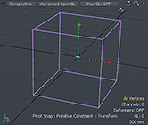
Geometry position constraints in Modo enable you to attach an item's center to a vertex edge or a polygon position onto another mesh item. Constraints can be used with modeled background geometry as a means of restricting what is created in the foreground. You first select the item you want constrained followed by the item you want to constrain to.
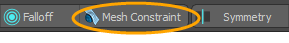
Constraints are found in the menu bar below the interface layout tabs.
The Mesh Constraints button is displayed in orange when a constraint is active. Selecting any mode enables the selected constraint and its associated settings appear in the upper portion of the panel, allowing you to customize how the constraint performs. The constraint affects the modeling procedure differently, depending on the type that is activated. For more information, see Constraint Modes.
To activate mesh constraint mode:
| 1. | Below the interface layout tabs, click the Mesh Constraint button to enable the default Background constraint mode. |
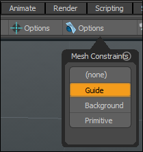
| 2. | Press Alt and click Options to view the Constrain to Background options. |
The Mesh Constraints dialog opens.
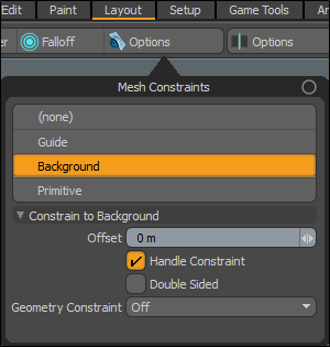
| 3. | Select one of the constraint modes: Guide, Background, or Primitive.. |
The icon button displays the name of your selected constraint mode.
To disable a mesh constraint mode:
• Press Alt and click the Mesh Constraint button and select None from the dropdown menu or click the constraint button highlighted in orange to dismiss it.
Constraint Modes
|
None |
Disables constraints. |
|
Guide |
When selected, you can define custom guide lines in the scene for visual reference or to enhance snapping. For information about, see Constrain to Guide. |
|
Background |
When selected, you can constrain or compel vertices of a foreground object against those of the background geometry during a transform or translation event. This is the most commonly used Constraint type. Background is the default Mesh Constraint mode. For information, see Constrain to Background. |
|
Primitive |
When selected, you can constrain or compel vertices of a foreground object against those of a user-defined primitive shape, during a transform or translation event. For information, see Constrain to Primitive. |
Constrain to Guide
Modo allows the creation of visual guide lines in the scene to be used as reference or to enhance snapping. You can create lines in 3D space and then use them as a snapping tool.
To create guide snaps:
| 1. | Press Alt and click Mesh Constraint and select Guide. |
Note: The Mesh Constraint button may display other text depending on the previous mode. See Constraint Modes.
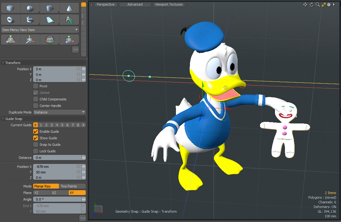
The Guide Snap properties are displayed in the Toolbar on the left panel.
| 2. | Click in any Model 3D viewport to create the guide snap at the intersection of the cursor and the Work Plane. |
The Enable Guide option in the properties is automatically enabled.
| 3. | In the Toolbox properties, enable Show Guide. |
| 4. | Use the blue handle to reposition the guide in the work plane and the blue circle to rotate. |
Tip: You can precisely control the position, plane, angle, and distance of the guide using the fields, as well as turn off the display of the guide, enable the guide, and turn the snapping on and off.
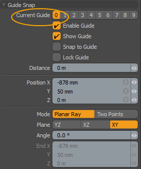
| 5. | In the Current Guide field, click on any number to change guide option used in the viewport. |
Constrain to Guide Properties
| Current Guide |
Allows you to choose which guide to create or edit by choosing from one of the ten options, each with independent settings. Tip: You can use polygon lines as guides. Watch this video to learn how to create custom guides in Modo. |
|
Enable Guide |
Enabled or disabled for snapping. |
|
Show Guide |
Visibility of the current guide. |
|
Snap to Guide |
Snapping to the guide. |
|
Lock Guide |
Once you have set the appropriate guide options, it can be helpful to lock the guide with this toggle to avoid accidentally changing the guide's path. When set, the main guide area changes from yellow to cyan. |
|
Distance |
Determines the length of the path. |
|
Position |
When using the Two Points mode of the guide function, the position option determines the start point of the guide. A straight line is drawn between this value and the end value that represents the guide line itself. When using the Planar Ray option, the Position value determines the home position for the guide. |
|
Mode |
You can define guides in two ways: Planar Ray for only planar facing guides, or Two Points for guides of any angle. • Planar Ray -You can define a single point, a plane on which the line sits, and an angle to determine the guide line. You can use the handle in the viewport to rotate the guide line. • Two Points - You can define two single points in 3D space and the guide line is created through the intersection of those two points. You can precisely position the line by dragging the two handles in the 3D viewport. |
|
Plane |
When choosing the Planar Ray guide mode, this option sets which plane (of the 3 axial planes) that the ray rests upon. |
|
Angle |
When choosing the Planar Ray guide mode, the Angle option determines the rotation of the guide around the Position point. |
|
End |
When choosing the Two Point guide mode, the End option determines the position of the second point. |
Constrain to Background
Setting Mesh Constraints to Background constrains the movement or creation of objects in the foreground layer from passing through any geometry in a background layer. This is the most common type of constraint.
Tip: Modo has various Item layers - Meshes, Locators, Cameras, Lights, Texture Locators, and Backdrop Items. For more information, see Items List.
Any item layer that is visible and selected is considered a foreground layer, and any layer that is visible but not selected is considered a background layer. Toggle layer visibility by clicking the eye icons in the left column of the Items list.
When active, the following attributes appear in the Properties panel under the active tool.
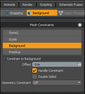
Constrain to Background Properties
|
Offset |
Allows you to define a distance away from a surface for constraint. This allows something like a tube being drawn over a background object to rest on the surface. If the tube has a diameter of 10 cm, applying a 5 cm offset rests the tube right on the surface as the tube is generated outward from its center. |
|
Handle Constraint |
For tools where a curve of some type is drawn, such as the Tube tool, curves, Bezier, or the Pen tool, the handles can be constrained also by enabling the Handle Constraints setting, otherwise, only the polygonal geometry is constrained. |
|
Double Sided |
When enabled, this setting treats background polygons as double sided, so geometry can be constrained regardless of the constraining surface's normal facing direction. |
|
Geometry Constraint |
Several options are available to define how Modo searches for the background geometry to constrain against. • Off - Temporarily disables the constraint. • Screen Axis - The constraining surface is evaluated by searching in a perpendicular direction to the current view position, stopping once it hits any geometry. This is the most basic constraint type. • Vector - Uses the translation/transform direction set by the active tool. If you have the Move tool active and start dragging the handle on the X axis, the constraint checks that direction to see what background elements it hits and then stops. If performing a bend, vertices move in many directions, as each vertex has its own vector, which is effectively the direction the vertex is currently moving toward. • Point - This constraint acts like a magnet, translated/transformed vertices are kept against the background geometry ensuring they are always resting directly on its surface. |
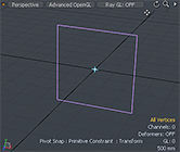
Constrain to Primitive
Setting the Mesh Constraint to Primitive creates a virtual primitive shape onto which tool handles can be constrained. Similar in concept to Background, however, no physical geometry needs to be present for the Primitive option.
When active, the following attributes appear in the Properties panel under the active tool.
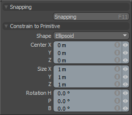
Constrain to Primitive Properties
|
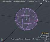
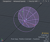
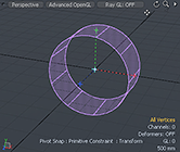
Shape |
You can choose from the various primitive shapes available for constraint: Plane, Ellipsoid, Cone, Cylinder and Cube.
|
|||||||||
|
Center |
Defines the center position of the virtual constraint element, based on the center of the bounding box. |
|||||||||
|
Size |
Defines the bounding box, which sets the size of the virtual constraint element. |
|||||||||
|
Rotation |
Defines the rotation amount for the virtual constraint element. |