B-Spline
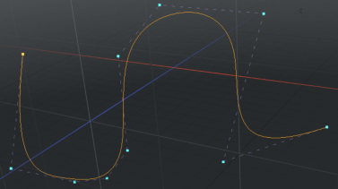
The B-Spline tool allows you to draw B-spline curves, which are spline curves defined by at least four vertices and a Weight Map. They provide better continuity than other spline curve types, because they don't go through any of their control points.
You can access the B-Spline tool in the following ways:
• In the Basic sub-tab of the modeling toolbox, by right-clicking the Pen button to reveal additional options.
• In the Curve sub-tab of the modeling toolbox.
• In the menu bar, under Geometry > Curve Palette.
Here's how to use the tool:
| 1. | Activate the tool in one of the ways described above. |
| 2. | Start clicking in the viewport to define control points for your curve. |
Tip: To create a closed curve, right-click on the first control point. Modo adds a curve segment between the first and last control points.
B-Spline Options
Once you drop the tool by pressing the spacebar, interactive editing within the tool itself is lost but you can re-activate the editing ability by selecting the curve in Polygons selection mode.
The following settings are available for the B-Spline tool.
|
B-Spline |
|
|---|---|
|
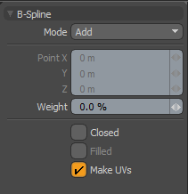
Mode |
There are several B-spline curve mode options: • Add - The default mode. When you click in the viewport, additional points are added to the curve. At each control point position, two handles extend out that allows you to adjust the curvature of the curve segment between vertices. While drawing, you can hover over any point or handle where it turns yellow. You can then click-and-drag the control point or handle to further edit the curve. Control points may be added mid-curve by selecting the preceding control, highlighting it yellow, and clicking the position where the new control point is desired (point order is defined by the initial order in which the curve was created. Press F before activating the tool to invert the order). • Edit - Freely click-and-drag any of the control points along the curve to change the look to the desired shape. • Delete - Click any of the control point along the curve to remove it from the B-spline. |
|
Point X, Y, Z |
If you want finer point control, you can assign specific XYZ values in these input fields for the currently-selected control point. |
|
Weight |
Specifies the weight of individual vertices. |
|
Closed |
Adds an automatic curve segment between the first and last control point positions, producing a closed curve. |
|
Filled |
When the Closed option is enabled, you can additionally enable the Filled option to create a render-able flat surface that is defined by the outlining curve itself. The resulting surface can be tagged like a polygon for adding material definitions. |
|
Make UVs |
Activates auto-generation of UV texture coordinates along the curve. The generated UV values are of a single vertical line (V axis in UV), positioning all the control point vertices evenly between 0 and 1. For example, this can be useful for applying a gradient to a rendered curve (the Render Curves option is available in the Mesh Item properties. |