Curve Particle Generator
The Curve Particle Generator tool is a point source that places particles along the length of a curve.
The Curve Particle Generator has an input for a source curve to describe the path of the particles. You can draw a curve in a mesh and assign the mesh to the Source Curve property. if you have multiple curves in the source mesh, you can select one using Curve Index.
This tool itself does not display the points it creates, to see the results you must use Replicators or Volumes. To use a Replicator, assign the Curve Particle Generator to the Point Source setting. For Volumes, use the Particle Source setting.
Orienting the Particles
When orienting particles along the curve, the Up Vector setting, used in combination with the Forward Axis, offers a flexible method of setting the required position. Let's use a simple mesh to show how these settings work:
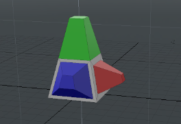
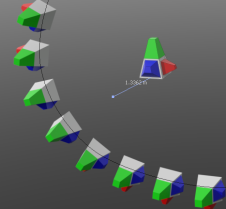
The mesh has colored parts to show its relationship to the world space. The red part points down the positive X-axis, green up the positive Y-axis, and blue down the positive Z-axis. This is our source mesh (prototype) for the replicator.
Forward Axis
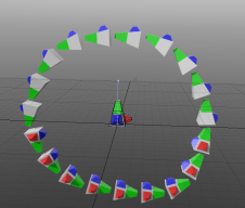
The Forward Axis determines the direction that the particle will face along the curve. In the first image below , the Forward Axis is set to Z. Observe how the blue part points forward along the curve. This is because the blue part points down the Z-axis in the prototype mesh. The image on the right shows the Forward Axis set to Y. This time the green part leads the way as it is the green section that is pointing up the Y-axis in the source mesh.

|
|
| Forward Axis is Z. | Forward Axis is Y. |
Up Vector
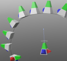
The Up Vector controls the secondary rotation of the particle. It describes the direction that the top of the particle will point, when placed along the curve. For example, if the Up Vector is pointing up the Y-axis, the top of each particle will attempt to point upwards as can be seen below. The Up Vector is indicated by the blue line, extending from the prototype. In all cases Forward Axis is set to Z.
|
|

|
| The Up Vector is pointing up, in the same direction as the green top. The particles also point upwards. | The Up Vector is pointing along the positive Z-axis. The top of the particles now point the same way. | The Up vector is pointing along the positive X-axis. |
Establishing the correct orientation depends on several variables, but in most cases it is a good idea to adjust the Up Vector to point through the plane of the curve. You can then rotate the prototype and change the Forward Axis to find the particle position that you want.
Note: The final position is subject to additional rotations by the Forward Axis, Particle Rotation and Rotation Shift.
In the image below, the prototype is inactive and can be seen wireframed towards the center of the image. The Up Vector is (0, 1, 0) , which points perpendicularly through the ground plane, and the Forward Axis is set to Z. Also, Align to Curve is off to keep the particles at the orientation of the prototype. Alternatively, you could adjust the orientation by rotating the prototype in polygon, edge, or vertex mode.
Warning: When rotating the source mesh you must be in polygon, edge, or vertex mode for the rotation to carry through to the particles. This because replicators ignore the item level rotation, position, and scale values from their prototypes.
Particle Scale and Particle Rotation
The Curve Particle Generator uses a Gradient Editor to determine variations in particle scale and rotation along the curve. The gradient can be displayed as a gray-scale color bar (where white represents the maximum value) or as a curve.
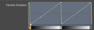
The image below shows an example for the Particle Rotation. The sawtooth pattern of the line indicates that successive particles are increasingly rotated until the maximum value (360o) is reached, the rotation then resets to 0o. This would appear as a smooth gradual increase in rotation along the curve, as a rotation of 360o is equivalent to a rotation of 0o.
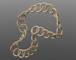
Note: This is the setting used to achieve the rotation in the chain, pictured at the top of this topic.
The image below shows variation in rotation and scale as depicted in a full-blown Gradient Editor. Each curve is labeled with the name of the property. The result is shown at the top of the image.
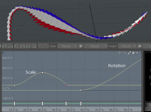
The properties are assigned to gradient channels. Gradients cannot be animated, which is why there is no channel animation button next to the property. However, there is a Scale Shift and Rotation Shift setting, which offsets the gradient and can be animated.
Using the Curve Particle Generator
You can add the tool from the Procedural Preset Browser, under the Particles > Point Clouds category. Click the Add Item button in the Item List to open the Preset Browser. The following steps show you how to use the Curve Particle Generator to create the wooden chain image shown above.
Note: If you already have a source mesh to replicate, and a curve in a separate mesh layer, skip to step 4.
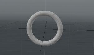
| 1. | First lets draw the source mesh, in this case let's use the Torus primitive to create the ring that is used as the link in the chain. Add a Torus to it's own mesh layer and size it to look similar to the one below. The position of the ring won't affect the result. |
| 2. | Add a new mesh layer to the Item List to hold the curve. |
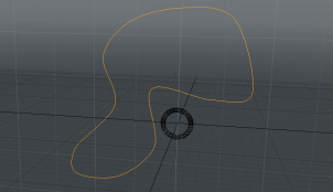
| 3. | Using the Curve tool, draw a path in the new mesh layer. Check Closed in the Tool Properties, or right-click the last control point to close the curve. The image below shows the curve used for the wooden chain (the inactive mesh for the ring can be seen in the background). |
| 4. | Now add a Curve Particle Generator to the Item List: Click Add Item and select Particles > Point Clouds. Double-click Curve Particle Generator. |
| 5. | To assign the source mesh (the ring) to the generator, ensure the Curve Particle Generator tab is selected on the generator's properties, and set Source Curve to the mesh containing the curve. |
| 6. | To see the particles add a Replicator: Click Add Item and select Locators > Particles. Double-click Replicator. |
| 7. | In the Replicator tab in the Item Properties, set Prototype to the mesh containing the ring. Set Point Source to Curve Particle Generator. |
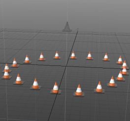
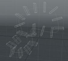
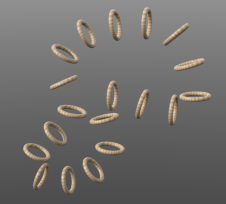
The images below show the 3D viewport and the rendered output (the source ring layer is hidden).
|
|
Tip: To preview the particles without rendering, set Ray GL to Full or Fast in the 3D viewport.
| 8. | To make the chain look like the one at the top of this topic, you will need to make some adjustments to the settings of the Curve Particle Generator as follows: |
• Increase the Point Count to 32.
• Set the Forward Axis to X.
• To make the links appear interlinked, adjust the Particle Rotation: Click on the small white triangle at the right of the Particle Rotation bar and select Medium Height View. This makes it easier to edit the rotation gradient.
Click the small square in the bottom right corner and drag it up to create a linear increase. Drag the square left to the center (top) of the editor to create a sawtooth type pattern similar to the one below. This should provide enough increase in rotation along the path to make the links appear interlinked.

| 9. | Finally, add the wood texture: Click the Shading tab to open the Shader Tree. Click Add Layer and select Textures > Wood. Ensure the Wood layer is above the Base Material. |
| 10. | Press F8 to open the Render Preview. |
Curve Particle Generator Properties
Edit the following properties to customize the behavior of the Curve Particle Generator.
|
Curve Particle Generator: Generator |
|
|---|---|
|
Source Curve |
Sets the curve to use as the path for the particles. |
|
Curve Index |
Selects the index of the curve to use from the source mesh. The index counts up from 0. |
|
Use All Curves |
Check this to use all curves from the source mesh. This overrides Curve Index. |
|
Mode |
Choose the particle disribution mode: • Point Count - Set the number of particles to place along the curve. • Spacing Distance - Set the distance between particles. The number of particles is then decided according to this distance. |
|
Point Count |
The number of particles to place along each curve. This is enabled when Mode is set to Point Count. |
|
Point Spacing |
The distance between each particle. This is enabled when Mode is set to Spacing Distance. |
|
Position Jitter |
The degree of random variation in the position of each particle. Using this you can create an uneven distribution of particles. |
|
Jitter Seed |
This is used to generate the random values used by Position Jitter. Try varying this to generate alternate random outcomes. |
|
End of Curve |
Sets how particles at the end of the curve behave. The following options are available: • Cluster - particles stop at the end of the curve • Wrap - wraps particles from the end of the curve to the start. • Project - particles exceeding the end of the curve, are placed on a straight line past the end. • Remove - particles exceeding the end of the curve are removed. |
|
Offset Percentage |
Sets the amount by which the particles are pushed up along the curve. At 0 %, the particles are unmoved. At 100 % the particles are pushed along by the full distance of the curve. If Wrap Around is unchecked, the particles will bunch up at the end of the curve. If it is checked, the particles will wrap back around and no bunching will occur. |
|
Start Percentage |
The amount along the curve length at which to place the first particle. |
|
End Percentage |
The amount along the curve length at which to place the last particle. |
|
Particle Rotation |
Sets the change in particle rotation along the curve (through the Forward Axis) by adjusting the Rotation Gradient channel. The horizontal axis represents the full length of the curve. The Particle Rotation can be set using one of five interface options. Click the small triangle on the left to select one of five interface options: • Open in Editor - Edit using the Rotation Gradient channel using the Gradient Editor. • Single Line - This is a line view using a grayscale gradient to represent the amount of rotation. Black indicates 0 % and white indicates 100 %. You can add a control point by middle-clicking on the line. To set the value of the control point, double-click on the control point to open the Set Key Value dialog, then edit the Value setting. • Shorter View - This shows a small graph representation of the gradient. You can drag control points and add new control points as you would in the Gradient Editor. • Medium Height View - This is the same representation as Shorter View but with more vertical space. • Taller View - The tallest graph view. |
|
Rotation Shift |
The amount along the curve path to shift the effect of the rotation. The gradient is offset by this amount from the start of the curve, though it wraps back from the end of the curve. |
|
Particle Scale |
Sets the change in scale of the particles along the curve by adjusting the Scale Gradient channel. The Particle Scale is set using the same interface options as the Particle Rotation. Click on the small white triangle on the left to reveal the options. |
|
Scale Shift |
The amount along the curve to shift the effect of the scale gradient. The gradient is offset by this amount from the start of the curve, though it wraps back from the end of the curve. Note: Both the Rotation Shift and Scale Shift support animation. |
|
Align to Curve |
Check this to orient the source mesh so that it is aligned to the curve at the point that it is placed. Leave this unchecked to maintain the original orientation. |
|
Forward Axis |
Selects the source mesh axis that is to face forwards along the direction of the curve. |
|
Up Vector X, Y, Z |
This vector defines the outward facing direction of the curve used for determining the particle rotations. Usually, this should be the vector crossing through the plane of your curve. |
Curve Particle Generator Schematic
The schematic node has a single input for the mesh containing the curve(s). You can wire the output to a Replicator or a Volume to draw the particles using a prototype mesh.
