Vertex Normal Map Tools
Modo provides a set of tools for working with vertex normals, found by clicking Vertex Map > Vertex Normal Tools. These tools let you control the shading on the mesh using a system of hard and soft edges, as defined by vertex normals. The normals generated by the tools are stored in a Vertex Normal Map, which overrides the vertex shading on the mesh generated by Modo's material settings.
The Vertex Map tools can be used to edit an existing vertex map, or if none exists, one is automatically added that holds the normals for the entire mesh. You can then select edges and edit the map as required. The Vertex Normal Map is not automatically updated if you alter the mesh, instead you need to manually update the map to recalculate the normals on your mesh.
Note: The soften/harden tools are context-sensitive and change based on the current selection mode (vertex, edge, or polygon). You can edit edges attached to a selection of vertices, edit a selection of edges, or edit edges bordering a polygon selection. The instructions below include variations for each selection mode.
Alternatively, you can adjust vertex color maps and vertex Weight Maps by opening the Paint layout, in the Toolbox on the left panel, open the Vertex Map Tools sub-tab, and Paint. For more information, see Vertex Map Tools.
 Soften Selected Edges
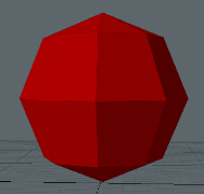
Click this to soften any selected edges. If no edges are selected then all edges are softened. Also, if you soften edges and there is no Vertex Map active on the mesh, a new Vertex Map is calculated for all normals, effectively smoothing the entire mesh.
If you soften any hard edges, the affected edges are removed from the HardEdges map. Softening all edges deletes the HardEdges map.
|

|
| A mesh without smooth shading. | All edges have been softened. |
 Vertex
Soften all edges with both end-vertices selected.
Shift+click to soften all edges connected to any of the selected vertices.
 Edge
Edge
Soften the selected edges.
 Polygon
Soften the edges at the boundary of the polygon selection.
 Harden Selected Edges
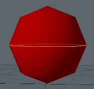
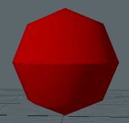
Click this to harden all selected edges. If no edges are selected then all edges are hardened. Hard edges are stored in an Edge Pick map called HardEdges. If no Vertex Map is present, one is added, and all other edges are soft.
|
|
| Softened edge mesh with central edges selected. | Selected edges have been hardened. |
 Vertex
Harden all edges with both end-vertices selected.
• Shift+click to harden all edges connected to any selected vertices.
• Ctrl+click to harden all edges with both end-vertices selected, and soften all other edges.
• Ctrl+Shift+click to harden all edges connected to any of the selected vertices, and soften all other edges.
 Edge
Edge
Harden the selected edges.
• Ctrl+click to harden the selected edges, and soften all other edges.
 Polygon
Harden the edges that lie on the boundary of the current polygon selection.
• Ctrl+click to harden the edges that lie on the boundary of the current polygon selection, and soften all other edges.
 Harden Edges at UV Boundary
Click this to harden the edges at the boundary of the selected UV Map. If no UV Map is selected, this option is grayed out.

|

|
| Mesh with all soft edges. | Edges at UV boundaries have been hardened. |
 Edge
Edge
Harden the edges that lie on the boundary of the currently selected UV map.
• Ctrl+click to harden the edges on the boundary of the UV map, and soften all other edges.
 Polygon
Harden the edges that lie on the boundary of the currently selected UV map, and are shared with other UV islands.
• Ctrl+click to harden the edges that lie on the boundary of the currently selected UV map, and are shared with other UV islands, and soften all other edges.
 Select Hard Edges
Select all edges marked as hard. Hard edges are stored in the HardEdges map.

• Shift+click to add all hard edges to the current edge selection.
• Ctrl+click to remove all hard edges from the current edge selection.
 Select Soft Edges
Select all edges not marked as hard. This is all edges except those stored in the HardEdges map.

• Shift+click to add all edges not marked as hard to the current edge selection.
• Ctrl+click to remove all edges not marked as hard from the current edge selection.
 Harden by Angle
Harden the smoothing across all selected edges that are between polygons at a sharper angle than the specified value (the Smoothing Angle). If no edges are selected, all edges are evaluated. Edit the Smoothing Angle before applying the command. You can change the Smoothing Angle and click the button to add hard edges to the HardEdges selection set. However, modifying the Smoothing Angle and hardening, does not remove any hard edges that were added as a result of prior operations.
Tip: This is useful for avoiding smoothing at hard edges, such as right angles.

|

|
| A chair mesh with soft edges. | All edges at seams sharper than 60° have been hardened. |
• Ctrl+click on this button to harden by the angle, and soften all other edges.
 Recalculate the Vertex Normal Map
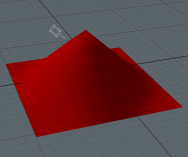
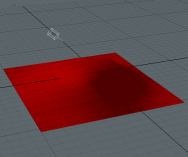
Recalculate the Vertex Normal Map following any changes to the shape of the mesh. This is recommended when you deform or edit a mesh, as the Vertex Normal Map does not automatically change to match the new shape.
|
|

|
| Original mesh. | The deformed mesh. The Vertex Normal map is unchanged. | The Vertex Normal map has been recalculated, and the shading now matches the new mesh. |
Note: All of the harden/soften commands, plus settings changes, call this command after they've configured the hard edge selection set.
 Convert to Hard Edges
Alt+click the recalculate button to convert the shading on the mesh to hard and soft edges. This is useful if you've imported the model from an external package, or loaded a scene that doesn't have a HardEdge selection set. This also attempts to convert meshes that are using Modo's own material smoothing, or an existing vertex normal map.
 Toggle the Vertex Normal Map
Ctrl+click the recalculate button to toggle the vertex normal map. This recalculates or deletes the vertex normal map.
Note: Because the vertex map is deleted and recalculated, the toggle option does not preserve vertex map data that has been transferred from another mesh.
 Vertex Normal Settings
Adjust the settings for the Vertex Map tools.
Some of the options deal with the weighting of the vertex normals. Each vertex normal is calculated as an average of the geometric normals of the polygons connected to it. Different characteristics can be selected to act as a weight for this calculation (such as polygon surface area). By using different weighting options, the vertex normal can be shifted to give more pleasing shading results.
|
Vertex Normal Settings |
|
|
Area Weighting |
The surface area of the polygon acts as a weight for the average, with larger polygons pulling the vertex normal more in-line with their own geometric normal. |
|
Sum Co-Planar Areas |
This causes the area of neighboring polygons to be added together, if the polygons are closely aligned. This option helps ensure that the same results are obtained from meshes that have been triangulated, compared to non-triangulated versions. |
|
Full Weighting |
This is similar to area weighting, but the vertex just takes the normal of the connected polygon with the largest surface area, rather than a weighted average. Note: If this option is enabled, Area Weighting and Angle Weighting settings are ignored. |
|
Angle Weighting |
The angle between the two edges of the polygon that meet the vertex, acts as a weight for the average, with wider angles pulling the vertex normal more in-line with the polygon's own geometric normal. |
|
Harden Edges |
If enabled, the recalculate command hardens the edges marked as hard. If disabled, all edges are assumed to be soft. |
|
Harden Smoothing Groups |
If enabled, the recalculate command respects all smoothing groups set on the mesh. If disabled, all polygons are assumed to share the same smoothing group. |
|
High Quality Normals |
If enabled, the recalculate command computes more accurate normals for non-planar polygons than are calculated using Modo's native implementation. Note: By default, for speed, Modo takes the normal of the triangle formed by the first three vertices of the polygon to be the polygon's geometric normal. For non-planar polygons, this may not be a truly accurate average of all of the geometric normals of all the triangles that make up the polygon. Enabling this option makes the recalculate command use all of the triangles for a polygon, averaging them out to get a better geometric normal for the polygon. |
Transfer Normals
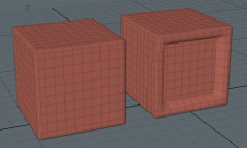
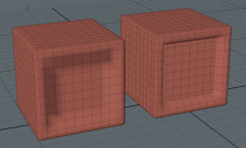
You can copy a Vertex Normal Map from a background mesh using the Transfer Normals button. This allows you to use the shading from a higher resolution mesh. Before using this command, select the foreground mesh, and make sure the background mesh is visible but unselected.
Note: This works by finding the closest (by distance) vertex-polygon pair on the background mesh to each vertex-polygon pair on the foreground mesh, and copies the normal value over.
The transfer happens in object space, so the items themselves can be moved apart, rotated, and scaled in Items mode and the transfer still works.
|
|
| Two mesh items. | The Vertex Normals have been copied from the right mesh to the left mesh. |
Morph to Normals
For each selected vertex, Morph to Normals takes the direction of the offset defined in the currently selected Relative Morph Map, and sets the vertex normal to point in that direction. If the offset has zero length, or the value is unset in the morph map, the normal is unchanged.
Before using this command, select the Relative Morph Map from the dropdown list.
Normal Map Name
The default name for the calculated Vertex Normal Map is vert_norms. To rename it, edit the name and click Rename.

Check Auto Rename to automatically assign the given name to the Vertex Normal Map after any edits.
Morph Push Tool
When baking normals, you can use a Morph Map as a Cage to determine the offset distance for the rays. The Morph Push Tool lets you alter the Cage size to customize the results of a bake. It also provides a more flexible alternative to Modo's Push tool for deforming morph maps.
Note: For more information on using Cages, see Bake from Object to Selected Texture
Compared to the Push tool, the Morph Push Tool has the following additional features:
• It always computes high quality normals to push along.
• It uses angle-weighted normals.
Note: Results are calculated by the same process that is used by the recalculate command.
These features ensure a cleaner push, with no discrepancies from non-planar polygons or differently triangulated meshes.
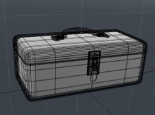
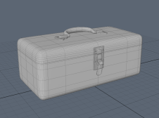
The images below show the Morph Push Tool used to create a cage for a low-poly mesh prior to baking.
|
|

|
| A foreground high poly mesh of a toolbox above a low poly mesh (selected). The low poly mesh also has an empty Morph Map. | The two meshes as viewed in Game Tools mode. | The Morph Map on the low poly mesh has been pushed using the Morph Push Tool to create a suitable Cage. |
Using the Morph Push Tool
The Morph Push Tool button is in the Morph Map Tools section of the Vertex Map tab. You must have a Morph Map for the tool to work.
| 1. | Click the Morph Push Tool button to open the tool. |
| 2. | Click in the 3D viewport to apply the tool. |
| 3. | Edit the parameters as required: |
|
Morph Push Tool |
|
|
Distance |
The distance to push the morphed position of each vertex. Tip: Click and drag in the 3D viewport to adjust the Distance. |
|
Absolute |
This makes the distance value absolute, rather than relative. Enable this to ensure that the distance each vertex is pushed is uniformly set to equal the Distance value, regardless of the distance that was already defined in the Morph Map. |
|
Push Existing Directions |
This ensures that the direction of the existing morph is used when pushing the vertices (instead of the default average normal). |
|
Angle Correction |
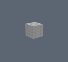
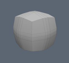
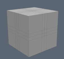
Enable this to retain the form of the mesh as best as possible when pushing. When enabled, the vertices on flat planes are pushed out by the Distance amount, while vertices on corners are pushed out more, to compensate for the averaged normal. |
|
|
|
|
A 1m cube with an empty Morph Map. |
The cube has been pushed by 1m without Angle Correction. |
The same 1m push but with Angle Correction. |
Morph 3D Viewport Options

|
Enable Morphs (Current Viewport) |
Allows the 3D Viewport to display the results of animated morphs. Enabling this option disables deformers. |
|
Draw Settings (Current Viewport) |
Specifies how you would like to draw Morph Maps. The following options are available when enabled: Drawing Style - Specify how you would like to draw Morph Maps. The following options are available: Default - Modo draws the traditional morphed mesh. Cage - Modo draws the base mesh and the morphed mesh as a cage. When this option is selected, additional properties are revealed:
Shade - When enable, draws a transparent morphed mesh as a cage. Shade Color - Specifies the color of the morph cage. Note: Only displayed when a Shader, Wireframe, or Vector is enabled. Shade Opacity- Specifies the opacity value of the morph cage. Wireframe - Draws the cage in wireframe mode. Wireframe Color - Specifies the color of the wireframe. Wireframe Opacity - Specifies the wireframe opacity. Vector - Draws line segments from the vertices of the base mesh to the corresponding vertices of the morph mesh. Vector Color - Sets the vector color. Vector Opacity - Sets the vector opacity. To display a morphed mesh, you need to select a morph map with Enable Deformers disabled. |
Cage View
You can quickly see the difference between an original mesh and the morphed version using the Cage View. This is useful for viewing Morph Maps that are used as Cages for baking.
Click the Add Cage View button to activate it. The original, unmorphed mesh is overlaid on the current geometry, and dashed lines are drawn between the unmorphed mesh and the morphed mesh.
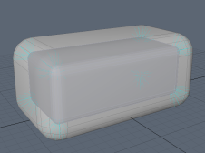
Enabling Cage View
To enable Cage View, you must configure the 3D viewport Properties.
| 1. | Hover the mouse over the 3D viewport, press O to open the 3D viewport Properties. |
| 2. | Enable Overlay Drawing. |
| 3. | Disable Enable Deformers. |
Cage View Settings
You can customize the Cage View appearance using the Cage View Settings panel. Click the Cage View Settings button to open the panel.
|
Cage View Settings |
|
|
Draw Base Mesh |
Draw filled polygons for the unmorphed mesh overlay. |
|
Draw Base Mesh Wireframe |
Draw the wireframe of the unmorphed mesh overlay. |
|
Draw Morph Offset Vectors |
Draw the dashed lines from the unmorphed vertex position to the morphed vertex position. |
|
Shade Base Mesh |
Shade the base mesh with some simple shading. This helps to better determine its form. |
|
Base Mesh Color |
The color of the polygons in the unmorphed mesh overlay. |
|
Base Mesh Wireframe Color |
The color of the wireframe of the unmorphed mesh overlay. |
|
Morph Offset Vectors Color |
The color of the dashed lines from the unmorphed vertex position to the morphed vertex position. |
|
Base Mesh Opacity |
The opacity of the polygons in the unmorphed mesh overlay. |
|
Base Mesh Wireframe Opacity |
The opacity of the wireframe of the unmorphed mesh overlay. |
|
Morph Offset Vectors Opacity |
The opacity of the dashed line from the unmorphed vertex position to the morphed vertex position. |
Mesh Tangents
The Vertex Map tab provides shortcut buttons to add tangent basis maps for various renderers. The following options are available:
• Create Current Preset Tangent Basis - Create a tangent basis map using the tangent command that is defined in the current normal map preset used in the Game Asset Exporter. See Editing Presets for how to choose and edit normal map presets for a project.
Note: The default preset is called None, and the default label for the button is Create Current Preset Tangent Basis. Changing the normal map preset changes the label accordingly.
• Create Mikk Tangent Basis - Create a tangent basis map using Mikk Tangent Space.
• Create Source Tangent Basis - Create a tangent basis map compatible with Valve's Source engine.
• Create Legacy Unity Tangent Basis - Create a tangent basis map compatible with the Unity Engine's legacy tangent basis standard.
If no UV maps are selected, the commands iterate over all active meshes, and tangent basis maps will be generated for all UV sets on each active mesh.
Note: A full list of tangent basis map generation commands can be found in the Tangent Basis Command list, under the Edit Normal Map Presets... section of the Export&Presets tab.
