Polygon Tools
The following are useful actions you might want to do using Polygon tools.
Split
To split polygons, select two vertices on a polygon to force an edge to be drawn between them. Vertices can also be selected in succession across polygons.
Triple
The Triple command subdivides any selected polygon with more than 3 vertices so that it consists only of triangle polygons. This can be very useful for preparing data to be saved in a format that does not support polygons with more than 3 vertices per polygon. It can also be useful for quickly breaking an n-gon down into triangles for similar export issues.
Alternatively, use the Mesh Operation, Triangulate, to subdivide polygons in your model. For more information, see Triangulate.
Convert to Quadrangles
Found in the menu bar under Geometry > Polygon > Quadruple or, within the Topo tab toolbox, the Convert to Quadrangles command takes a series of vertices from an N-gon and creates a row of regular four sided (quadrangle) polygons. This is useful in creating quad strips, especially when re-topologizing a model. Using the Pen tool, lay down two opposing rows of vertices, then invoke the Convert to Quadrangles command and Modo automatically adds edges spanning between the opposing vertices, making quad polygons.
Spin Quads
The Spin Quads command changes where your edges are attached within the geometry. For example, if you select two adjacent polys, this command spins them so that they attach to different points while leaving them in place. It changes the flow of your polygons while maintaining the surrounding mesh. Spin Edges does the same thing on an edge level, however, you can select one edge and spin it so that it bisects two polygons differently. Spin Quads only works with two polygons with the same edge number.
These tools are found on the Edge and Polygon tabs of the Modo Tools toolbar, under the Commands groups.
Flip
The Flip tool reverses the direction of selected polygons. Polygons are typically single sided and, as such, are only visible from one direction. The visible side is determined by the direction of the normal. The direction of a polygon is initially determined by the order in which its vertices were created, or selected, to make the polygon. The Flip tool effectively re-orders those vertices so that the polygon faces the opposite direction. For linear polygons, such as curves, the Flip tool reverses the order to force the curve to run the opposite direction.
Align
The AlignPolygons tool attempts to automatically make all polygons face the same direction. Use this when you have mesh geometry with polygons that have face normals facing both toward and away from the view. Align Polygons uses the first polygon you select as the model. It attempts to match the face normal direction of that polygon.
Make Curve Fill
Found under the Commands section of the Polygons toolbox, the Make Curve Fill command converts a closed curve, or a series of connected curves, into a renderable flat polygon's surface. It works with both Bezier or Spline curve types and is especially useful for rendering simple vector graphics.
Tip: Bezier curves for curve fill polygon types can be created by importing an .eps file, or by converting text to Beziers using the Convert Text to Beziers command. Curve fill polygons can also be created by turning on the Fill option on the Curve and Bezier tools.
Merge
The Merge Polygons option combines selected polygons into a single polygon of n-number of sides. Essentially, it removes all interior edges, so the multiple polygons can be treated as a single polygon.
Note: More complex selections merge as many polygons together as necessary to remove the target edges. If all the edges that use a vertex are deleted, then the vertex is deleted as well. It may be possible for you to specify selections that cannot all be consistently deleted. In that case the operation does the best that it can without leaving "spikes", which are edges entirely internal to a single polygon.
To open the Merge Polygon tool:
• On the left panel, open the Polygon tab, under the Commands section, click on the Reduce pulldown, and select Merge.
• On the menu bar select Geometry > Polygon > Merge.
• On the right panel, open the Mesh Ops tab, click Add Operator, and double-click Mesh Operations > Polygons > Polygon Merge.
Using a Procedural Polygon Merge
The procedural version of the merge tool, Polygon Merge, takes a connected selection of polygons and merges them into a single polygon. For example, you can create several procedural mesh operators in the Mesh Operations list, apply the Polygon Merge tool and then specify which Select by Previous Operation to merge that selection of polygons into a single polygon. The original polygons are retained.
In this simple example, we have selected a number of polygons and applied the Polygon Merge tool. A single polygon is created to our selections.
The following is an example of adding a number of mesh operations and then applying the Polygon Merge to a Select by Previous Operation.
| 1. | On the left panel, Shift+ click on the |
| 2. | Under the layout menu bar, click Edges. |
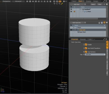
| 3. | Press Shift + click two edges on the middle of the cylinder and press L to select the entire loop. |

| 4. | On the right panel, open the Mesh Ops tab, clickAdd Operator, and select Mesh Operations > Edge > Edge Split. |
| 5. | In the Properties panel, open the Edge Split tab, set the Gap value to 875mm, and enable Cap Sections. |
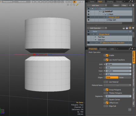
| 6. | On the right panel, click Add Operator, and double-click Mesh Operations > Polygon > Polygon Bevel. |
| 7. | Expand the Polygon Bevel item, click (Add Selection), and double-click Mesh Operations > Selection > Select by Previous Operation. |
| 8. | In the properties, set Source Item to Edge Split and set Name to Caps. |
| 9. | In the Mesh Operations list, select Polygon Bevel and click + drag the blue handle to apply a bevel. |
| 10. | On the right panel, click Add Operator, and double-click Mesh Operations > Polygons > Polygon Merge. |
| 11. | Expand Polygon Merge > Selection, click (Add Selection), and double-click Select by Previous Operation. |
| 12. | In the Properties tab, set the Source Item to Polygon Bevel, and the Name to Front. |
Collapse
The Collapse command removes the selected element without destroying the integrity of the geometry. Any select polygon, edge, or vertex is deleted but no hole is left behind. Instead, the mesh heals, closing any gaps by merging the neighboring elements together.
Polygons: On the Polygons tab of the Modo Tools toolbar > Commands > Reduce > Collapse.
You can also select whatever geometry you wish to collapse and then choose Geometry > Collapse.
For more examples, see Reduce Collapse Tools.
Collapse Selection
The Collapse Selection command removes the selected element without destroying the integrity of the geometry. Any select polygon, edge, or vertex is deleted but no hole is left behind. Instead, the mesh heals, closing any gaps by merging the neighboring elements together and merging together at the center.
Polygons: On the Polygons tab of the Modo Tools toolbar > Commands > Reduce > Collapse Selection.
For more examples and information about Collapse Selection, see Reduce Collapse Tools.
Remove
The Remove Polygon command deletes the selected polygons, completely removing them from the selected Mesh Item layer. The command is found within the Modeling tabs under the Polygon toolbox, or in the menu bar under Geometry > Remove. You can also simply press the Backspace key on the keyboard.
Unify
Unify Polygons lets you merge two polygons into a single polygon when you have two polygons that are in exactly the same position and the polygons share the same vertices.
To access the Unify Polygons tool:
• On the left panel of the Model layout, open the Polygon tab , click the dropdown arrow next to Reduce, and click Unify.
• Alternatively, on the right panel open the Mesh Ops tab, click Add Operator, and double-click Mesh Operations > Polygon > Polygon Unify.
• Alternatively, on the top left corner of the interface, click the ![]() Schematic palette icon , click Add..., and double-click Mesh Operations > Deform > Polygon Unify.
Schematic palette icon , click Add..., and double-click Mesh Operations > Deform > Polygon Unify.
Polygon Unify Option
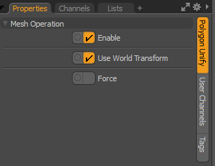
• Enable - Enables or disabled the Push tool.
• Use World Transform - Sets the coordinates from Model Space to World Space where vertices are defined relative to an origin common to all the objects in a scene.
• Force unify - Forces polygons to merge together to create one polygon.
Convert Text to Bezier
Precisely as the name implies, this command converts geometry created with the Text tool to Bezier curves. To use, type out a line of text using the Text tool, and then invoke the menu bar command Geometry > Convert Text to Bezier. Converted text becomes a collection of merged Bezier curves and can be further edited using the Bezier Curve tool. If desired, the Make Curve Fill command converts the curves back into render-able shapes.
Detriangulate
Converts triangle pairs to quadrangles by deleting edges to share triangle pairs. This conversion tool evaluates the flatness of the geometry.
• For Direct Modeling, the Detriangulate tool is found under the Geometry > Polygon menu. To enable this tool, first apply the Automatic Retopology Tool.
• For Procedural Modeling, the Detriangulate tool is found under the Mesh Ops tab. Click Add Operator and select Mesh Operations > Polygons > Detriangulate.
For more detailed information, see Detriangulate.