Search is based on keyword.
Ex: "Procedures"
Do not search with natural language
Ex: "How do I write a new procedure?"
Switch Modifier

The Switch channel modifier works similarly to the String Switch and Numeric Switch Modifier. You can connect multiple inputs to a single connection, and use an index channel to specify which of the inputs is written to the output. However, unlike the String and Numeric Switch modifiers, Switch can operate on any value type.
If the types of the objects connected to the Inputs and Output are different, they are automatically converted to the Output type, when possible. For example, if your inputs contain Boolean, Matrix, and Float values, but the output is a string, the input values are all converted to strings.
Using Switch
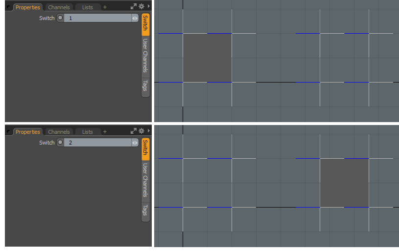
In the example below, the Switch modifier takes two arrays and creates a polygon using one of them, depending on which array's index is selected in the switch.
| 1. | In the Schematic layout, click Add..., then navigate to Channel Modifiers > Other, and double-click Switch. |
This adds the Switch node to the Schematic.
| 2. | Connect the inputs to the node's Inputs channel. In this case, we use two arrays generated from locators using the Array Modifiers modifier. |

| 3. | Connect the output nodes to the Switch node's Output channel. Here we have two Create Polygon operations, that generate polygons based on array positions. |

| 4. | Click the Switch node in the Schematic, and in the Properties panel on the right, set the Switch property to the index of the output you want to see. In this case, setting Switch to 1 draws a polygon using the first set of locators, while choosing 2 draws a polygon using the second set of locators. |
Note: Index assignment depends on the order you connected the nodes to the Switch node's Inputs channel.

Sorry you didn't find this helpful
Why wasn't this helpful? (check all that apply)
Thanks for taking time to give us feedback.