Search is based on keyword.
Ex: "Procedures"
Do not search with natural language
Ex: "How do I write a new procedure?"
Gradient Modifiers
Gradient Modifiers read an incoming gradient, and output a modified gradient curve. For example, if the incoming gradient is linear from 0.0 to 1.0, and the modifier is a Gradient Offset node with a value of 1.0 in the Y axis, the resulting gradient is a linear gradient from 1.0 to 2.0. Gradient Modifiers can be created like any standard channel modifier in the Schematic viewport, and their inputs and outputs can be connected to Gradient channels on any item, including Gradient user channels.
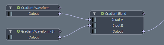
Gradient Blend
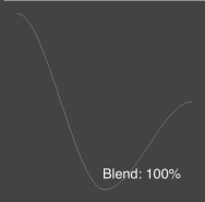
The Gradient Blend modifier performs a linear interpolation between two gradients.
Example
|
|
|
|
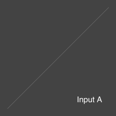
Input A is a linear gradient. |
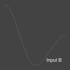
Input B is a curved gradient. |
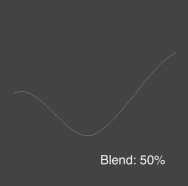
With a blend amount of 0%, the linear gradient is the output. With a blend amount of 100%, the curved gradient is the output. If the blend amount is 50%, the output is a mix of the linear and the curved gradient.

|
|
|
Gradient Blend Properties
|
Channels on the Node by Default |
|
|
Input A |
The gradient to blend from. |
|
Input B |
The gradient to blend to. |
|
Output |
The blended gradient. |
|
Properties Panel |
|
|
Mode |
The type of value used for modulating the interpolation. The following options are available:
|
|
Blend |
When Mode is set to Scalar, specifies the amount to blend between Input A and Input B. |
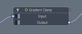
Gradient Clamp
The Gradient Clamp modifier clamps the gradient output value, ensuring that the value never exceeds the specified minimum and maximum range.
Example
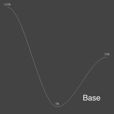
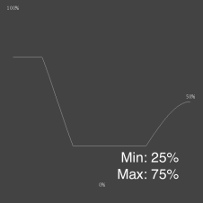
The following images show a gradient clamped at a Minimum Value of 0.25 and a Maximum value of 0.75.
|
|
|
|
The input gradient. |
The clamped gradient. |
Gradient Clamp Properties
|
Channels on the Node by Default |
|
|
Input |
The gradient to clamp. |
|
Output |
The clamped gradient. |
|
Properties Panel |
|
| Minimum Value | The lower end of the clamped range. |
| Maximum Value | The upper end of the clamped range. |
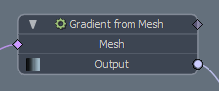
Gradient from Mesh
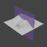
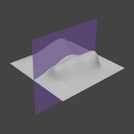
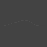
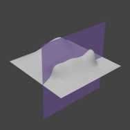
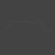
The Gradient from Mesh modifier generates a gradient from a mesh layer. It maps the height of the mesh in either the X, Y, or Z axis to the value of the gradient.
The modifier takes a slice through the input mesh, and raycasts into the slice to extract the height of the surface. You can specify the axis and offset for the slice, as well as animate it, allowing the slope of the gradient to be modified over time.
|
|
|
|
|
|
|
Channels on the Node by Default |
|
|
Mesh |
The mesh used for producing the gradient. |
|
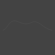
Output |
The computed gradient. |
|
Properties Panel |
|
|
Axis |
The axis along which the raycast is projected. The height of the mesh in the axis determines the value of the gradient. |
|
Slice Axis |
The axis along which the mesh is sliced. U and V maps to the two axes not specified as Axis for raycasting. For example, if the raycasting axis is Y, U and V in the Slice Axis represent X and Z respectively. |
|
Slice Offset |
The offset along the slice axis to slice the mesh. Animating this value moves the slicing plane forwards and backwards, animating the value of the gradient. |
|
Range Minimum/Range Maximum |
The bounding box of the mesh is read as the extremes of the gradient, but the way they map to gradient values is determined by the Range Minimum and Range Maximum options. Changing these values control how the smallest and largest extremes of the bounding box map to the smallest and largest time values in the gradient. |
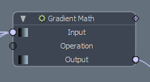
Gradient Math
The Gradient Math modifier performs basic math operations on any number of gradient inputs.
Example
Let's take these three input gradients:
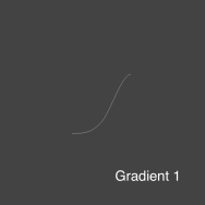
|
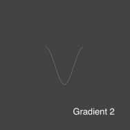
|
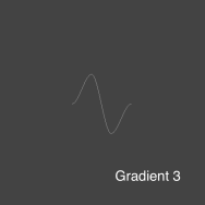
|
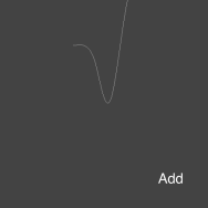
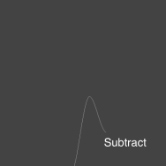
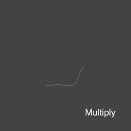
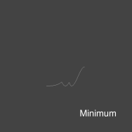
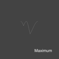
The following results are generated using each math operation:
|
|
|
|
|
|
|
Channels on the Node by Default |
|
|
Input |
The gradients to perform math operations on. This input allows multiple connections. |
|
Operation |
The mathematical operation to perform. The available options are: • Add - Adds the gradients to one another and outputs the computed result. • Subtract - Subtracts each gradient in turn, from a flat gradient at zero. • Multiply - Multiplies the gradients by one another and outputs the computed result. • Minimum - Returns a gradient containing the smallest values picked from each of the input gradients. • Maximum - Returns a gradient containing the largest values picked from each of the input gradients. • Average - Returns the average of all input gradients. |
|
Output |
The computed gradient. |
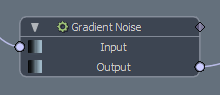
Gradient Noise
The Gradient Noise modifier applies Perlin Noise to an existing gradient. The modifier provides control over both noise amplitude and frequency.
|
|
|
|
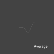
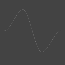
The input gradient. |
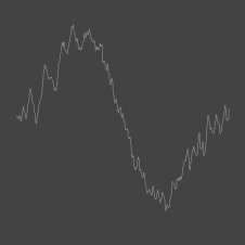
The gradient with noise applied to it. |
Gradient Noise Properties
|
Channels on the Node by Default |
|
|
Input |
The source gradient. |
|
Output |
The computed gradient with noise applied. |
|
Properties Panel |
|
|
Frequency |
Determines how regularly the noise occurs per second. |
|
Amplitude |
Controls how strong the noise offsets the original base gradient. |
|
Seed |
Seeds the randomness of the noise generator. Animating this value animates the noise. |
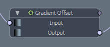
Gradient Offset
The Gradient Offset node offsets all the values in a gradient equally, either by offsetting the value in Y, and/or the time the value is sampled in X.
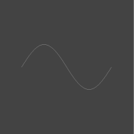
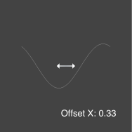
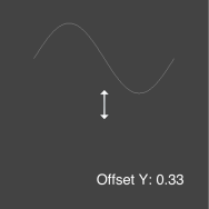
Example
This example shows the source gradient offset by 0.33 on X and by 0.33 on Y.
|
|
|
|
Channels on the Node by Default |
|
|
Input |
The gradient to offset. |
|
Output |
The offset gradient. |
|
Properties Panel |
|
|
Offset X |
Offsets the gradient value in X. This offsets the sample time, so reading the gradient at a specific time sample remaps the time sample to read the input gradient at a different time. |
|
Offset Y |
Remaps the gradient value, adding the Offset Y value to the input gradient sampled value. |
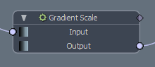
Gradient Scale
The Gradient Scale modifier scales a gradient either in the Y axis, modifying the gradient's value, or the X axis, modifying the time of each value. You can also control the pivot point for each axis the scaling is performed in.
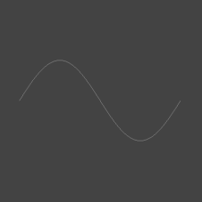
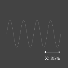
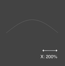
Example
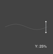
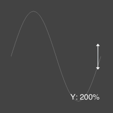
This example shows the input gradient scaled on the X and then the Y axis by 0.25 and 2.0.
|
|
|
|
|
|
Gradient Scale Properties
| Channels on the Node by Default | |
| Input | The gradient to scale. |
| Output | The scaled gradient. |
| Properties Panel | |
|
Amount X/Y |
The amount the input gradient is scaled in the X/Y axis. Changing X modifies the sample time of each value in the gradient. Changing Y increases or decreases the gradient values. |
|
Center X/Y |
The pivot point to perform the scale in the X/Y axis. The gradient is scaled from this position. |
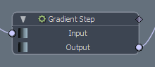
Gradient Step
The Gradient Step modifier rounds values in a floating point gradient to their nearest whole number. For example, 0.25 becomes 0.0, and 0.6 becomes 1.0. This can introduce a step pattern to gradients that cover a large range of floating point values.
Example
In this example, the base gradient has a Maximum Value of 5.0 and a Minimum Value of -5.0. This introduces 11 steps across the range, as every value between -5.0 and +5.0 (including 0.0) is rounded to their nearest whole number.
|
|
| The source gradient. | The output gradient. |
Gradient Step Properties
|
Channels on the Node by Default |
|
| Input | The input gradient. |
|
Output |
The stepped gradient. |
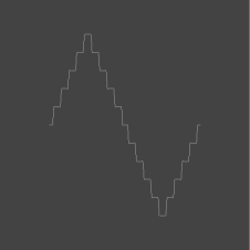
Gradient Waveform
The Gradient Waveform modifier generates a gradient from four standard waveform presets: Sine, Square, Triangle, and Sawtooth. You can use this to create regular repeated gradients.
|
|
A sinusoidal waveform that describes a smooth periodic oscillation from one extreme of the amplitude to the other. |
|
|
A square wavefrom that rounds to the nearest amplitude value. |
|
|
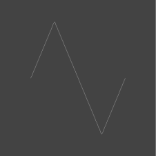
A triangle waveform that blends in linearly from one extreme of the amplitude to the other. |
|
|
A sawtooth waveform that blends linearly to the positive extreme of the amplitude, and then snaps back to the negative extreme of the amplitude. |
Gradient Waveform Properties
|
Channels on the Node by Default |
|
|
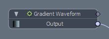
Output |
The gradient containing the waveform. |
|
Properties Panel |
|
|
Type |
The type of waveform to generate:
|
|
Amplitude |
The highest and lowest peak of the waveform. A value of 1.0 produces a low of -1.0, and a high of 1.0. |
|
Frequency |
Determines how regularly the oscillating motion occurs per second. A value of 1.0 produces one up and down cycle per 1.0 time step. |
|
Offset |
Offsets the gradient output value in the Y axis. |
Sorry you didn't find this helpful
Why wasn't this helpful? (check all that apply)
Thanks for your feedback.
If you can't find what you're looking for or you have a workflow question, please try Foundry Support.
If you have any thoughts on how we can improve our learning content, please email the Documentation team using the button below.
Thanks for taking time to give us feedback.