Search is based on keyword.
Ex: "Procedures"
Do not search with natural language
Ex: "How do I write a new procedure?"
Curve Sweep
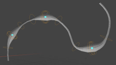
The Curve Sweep mesh operation is similar to Curve Extrude, but provides better control and a more streamlined workflow for procedurally extruding geometry along a curve. It is most commonly used when working with the Lace Item to generate lacing.
Note: For more information on lacing, see Lace Item.
Using Curve Sweep
To use the tool, you need at least two mesh layers for the following:
• The curve used as the path
• The Curve Sweep operation and the geometry used as the shape for the sweep operation.
The shape geometry can also be located in a third, separate mesh layer, or can be a preset.
Tip: To add a new mesh layer, press the N key, or in the Item List, click Add Item, and under Items, double-click Mesh.
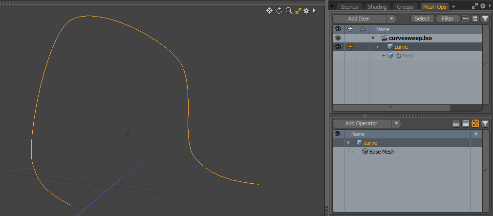
| 1. | Create a curve in an empty mesh. |
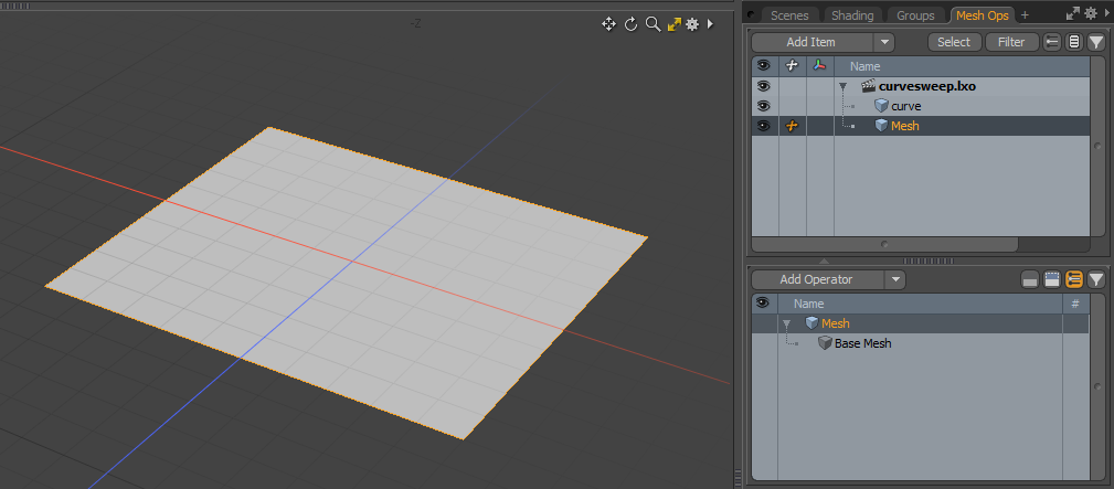
| 2. | Add a new mesh, or select one in the Item List. |
| 3. | Add the geometry you want to use to sweep along the curve. For example, a square. |
| 4. | Staying in the same mesh where you've just added your geometry, in the Mesh Ops tab, click Add Operator, and under Mesh Operations > Curves, double-click Curve Sweep. |
Note: If you're working in a layout where the Mesh Ops tab is not visible by default, click the + button on the right of the tab names, and select Data Lists > Mesh Ops.
The Curve Sweep mesh operation is added to the Mesh Operations list. And its properties open on the lower right panel.
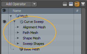
Expanding the mesh operation by clicking the arrow in front of it reveals the operation's inputs.
You can set up the following here:
• Alignment Mesh - You can use geometry in another mesh to determine the alignment of normals along the curve. The mesh containing the geometry can be added here.
• Path Mesh - The path to sweep along. This is the mesh containing your curve.
• Shape Mesh - The shape to use for the sweep operation. This is the mesh containing the geometry you want to duplicate along the path. If your geometry is in the same mesh layer as the Curve Sweep operation, you don't need to specify this.
• Sweep Shapes - You can use more than one shape for the sweep operation. This input allows you to specify additional shapes.
| 5. | In the Curve Sweep operation's Properties panel, set Path to the mesh where your curve is. |
If you have multiple curves in your mesh and you only want to use some of them, specify the Curve Index. For example, if you have four curves in your mesh, but you only want the first two to be affected by the Curve Sweep, enter '0,1'.
| 6. | Make sure that Extrude Shape is set to Current Mesh. |
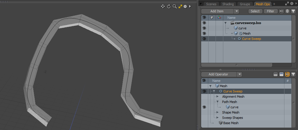
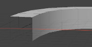
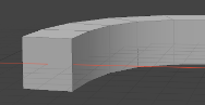
The geometry is duplicated along the length of the curve.
For more information on other properties you can adjust, see Curve Sweep Properties.
Using a Shape in a Separate Mesh Layer
If the shape to duplicate is not in the same mesh layer as the Curve Sweep operation, you need to specify the mesh in the Curve Sweep Properties.
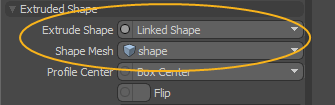
Under Extruded Shape, set Extrude Shape to Linked Shape, and Shape Mesh to the mesh layer where your shape is.
The geometry in the specified mesh is duplicated along the length of the curve.
Using a Preset as Shape
In addition to using geometry, you can use one of the Profile presets to sweep along the curve. Once you've added the operation and specified the curve, follow these steps:
| 1. | In the Curve Sweep Properties, set Extrude Shape to Preset, |
A Profiles preset browser opens below the properties.
| 2. | Click one of the presets. |
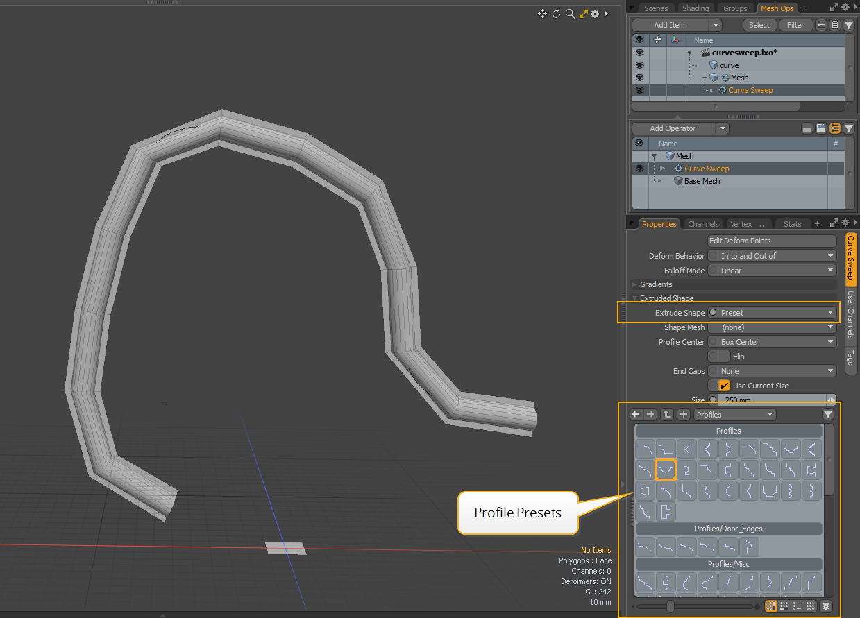
The selected shape is duplicated along the length of the curve.
Using Multiple Shapes
The Curve Sweep mesh operation allows you to use multiple shapes to sweep along different sections of the curve, and blend from one shape into another.
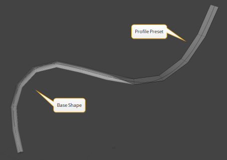
Once you've added the operation and specified the curve and base shape, follow these steps:
| 1. | In the Mesh Operations list, expand the Curve Sweep operation, then expand its Sweep Shapes input and click (Add Sweep Shapes). |
This opens the Add Operation dialog.
| 2. | Under New, double-click Sweep Shape Input. |
The Sweep Shape Input operation is added to the Mesh Operations list, and its properties open in the Properties panel.
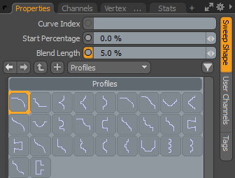
| 3. | Select a Profile preset, and specify the following: |
|
Curve Index |
Specifies the curve to be used. If you have only one curve in your scene, you don't need to use this. |
|
Start Percentage |
The point along the curve where Modo starts using the selected shape instead of the base shape. |
|
Blend Length |
Specifies how far along the curve the two shapes are blended. The lower the value, the more abrupt the change is from one shape to the other. |
You can add as many Sweep Shape Inputs as you like.
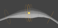
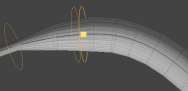
Adding and Editing Deform Points
You can deform points of the swept curve using the Edit Deform Points tool, located in the Curve Sweep operation's Properties panel.
To use the tool:
| 1. | Add and set up your Curve Sweep mesh operation, as described in Using Curve Sweep. |
| 2. | Click Curve Sweep in the Mesh Operations list to open its properties in the Properties panel. |
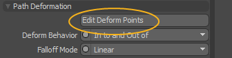
| 3. | Under Path Deformation, click Edit Deform Points. |
| 4. | The Tool Properties appear on the left panel. If you're working in the Modo layout, click the Tool Properties button or press K to reveal them. |
| 5. | Shift+click on the curve to place deformation points. |
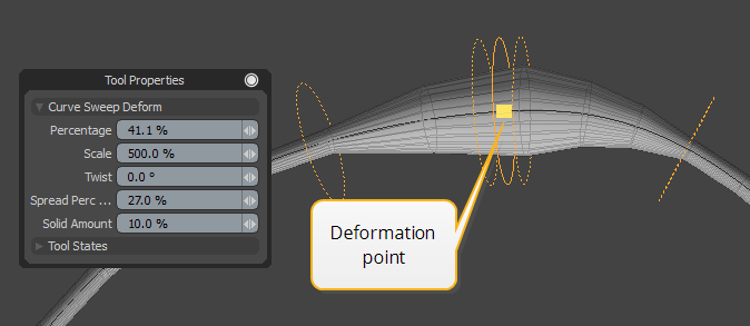
| 6. | Edit the deformation values in the Tool Properties or in the 3D viewport. |
| Property | Keyboard Shortcut | Description |
|---|---|---|
|
Percentage |
Click-and-drag |
The position of the deformation point along the curve. |
|
Scale |
Right-click-and-drag |
The strength of the deformation. |
|
Twist |
Ctrl+right-click-and-drag |
The rotation around the sweep path's tangent applied to the extruded geometry. |
|
Spread Percent |
Ctrl+click-and-drag |
The range of the deformation's effect. |
|
Solid Amount |
|
The amount of the spread area that the deformation is applied to at 100%. Anything outside of this range is blended into or out of based on the falloff and deformation mode settings. |
| 7. | Adjust the Path Deformation options in the Curve Sweep Properties, if needed. For more information on these options, see Path Deformation. |
You can remove a deformation point by right-clicking it.
Curve Sweep Properties
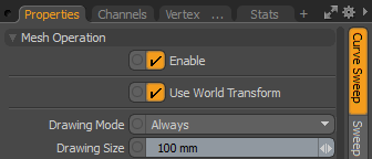
Selecting the Curve Sweep mesh operation in the Mesh Operations list opens its properties on the lower right panel.
Mesh Operation
|
Enable |
Enables or disables the mesh operation. |
|
Use World Transform |
Sets the coordinates from Model Space to World Space where vertices are defined relative to an origin common to all the objects in a scene. |
|
Drawing Mode |
When deformation has been applied along the sweep, these points can be drawn in the viewport. This option specifies when to draw the deformation points. You can set it to Always, only when they are Selected, or disable it completely by selecting None. |
|
Drawing Size |
Specifies the size of the drawn deformation controllers. |
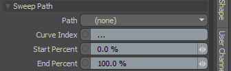
Sweep Path
|
Path |
The mesh containing the curve or curves to sweep along. |
|
Curve Index |
The index of the curves to sweep along. If you only have one curve in your mesh layer, you don't need to specify this. |
|
Start Percent |
The percentage along the curve to start creating geometry. |
|
End Percent |
The percentage along the curve to stop creating geometry. |
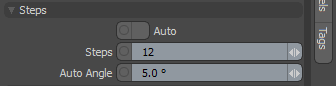
Steps
|
Auto |
Automatically determines the number of steps to use based on the Auto Angle. |
|
Steps |
When Auto is disabled, determines the number of steps along the curve path, controlling the number of segments of the resulting sweep. |
|
Auto Angle |
The maximum amount of curve along the sweep path allowed without adding a step when Auto is enabled. |
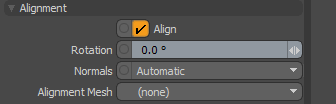
Alignment
|
Align |
When enabled, Modo aligns the swept geometry to the path. |
|
Rotation |
Rotate the geometry around the tangents along the path by the specified amount. |
|
Normals |
Specifies the way the path normals are determined. • Automatic - Generates smoothly interpolating normals along the path. • Mesh Normals - Uses the polygon normal from an alignment mesh. • Curve Direction - Aligns the normals towards the curve found in the selected alignment mesh. The normal can be the direction to the closest point on the other curve, or the direction to the point on the other curve with an identical percentage along the curve. • Path Normal - Aligns normals to the average normal of the path curve. |
|
Alignment Mesh |
Specifies the mesh used when Normals is set to Mesh Normals or Curve Direction. |
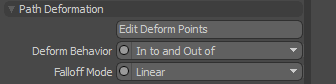
Path Deformation
|
Edit Deform Points |
Activates the Sweep Deformation tool. For more information on how to use the tool, see Adding and Editing Deform Points. |
||||
|
Deform Behavior |
Specifies the way the deformation is applied. • In to and Out of - Blends from undeformed into deformed, then back to undeformed based on the Spread Percent. • Blend In to - Blends into the deformed shape and propagates the effect along the rest of the curve.
|
||||
|
Falloff Mode |
The falloff shape when blending between deformed and undeformed geometry. The available options are: • Linear • Ease In • Ease Out • Smooth |
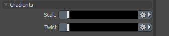
Gradients
|
Scale |
Drives the scale of the extruded geometry over the length of the curve using a gradient. |
|
Twist |
Drives the twist of the extruded geometry over the length of the curve using a gradient. |
Note: For more information on working with gradients, see Gradient Editor.
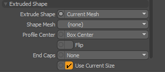
Extruded Shape
|
Extrude Shape |
The base shape to extrude. • Current Mesh - The mesh where the Curve Sweep operation is located. • Linked Shape - A different mesh linked through the Shape Mesh input. For more information, see Using a Shape in a Separate Mesh Layer. • Preset - A Profile preset. Selecting this option opens a preset browser in the panel. For more information, see Using a Preset as Shape. • Polygon Strips - Uses strips of polygons to sweep along the curve. |
||||
|
Shape Mesh |
When Extrude Shape is set to Linked Shape, this controls which mesh is used. |
||||
|
Profile Center |
The bounding box pivot of the shape to extrude. |
||||
|
Flip |
When enabled, inverts the faces of the generated polygons. |
||||
|
End Caps |
Creates closed polygons on the ends of the sweep.
The available options are: • None - Both ends are left open. • Start - Closing polygons are created at the start. • End - Closing polygons are created at the end. • Both - Closing polygons are created on both ends. Note: The polygon faces might be inverted. In such cases, enable Flip to get the expected result. |
||||
|
Use Current Size |
Use the current size of the shape to extrude. |
||||
|
Size |
Set a different size for the extruded geometry if Use Current Size is disabled. |
Curve Sweep in the Schematic
You can work with the Curve Sweep mesh operation in the Schematic viewport too.
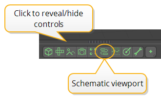
To open the Schematic viewport:
• In the Modo layout, click the thin gray line below the 3D viewport, and click the Schematic viewport ![]() button.
button.
OR
• Switch to the Setup layout from the menu bar by clicking Layout > Layouts > Setup.
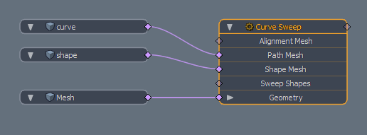
To add the Curve Sweep node:
| 1. | Click Add..., and under Mesh Operations > Curves, double-click Curve Sweep. |
This adds the node to the viewport and opens its properties on the lower right panel.
In the Item List, select the mesh layer containing your curve and the one containing the shape geometry if it's separate.
| 2. | In the Schematic viewport, click Add Selected. |
Your meshes are added to the Schematic viewport.
| 3. | Connect the curve mesh to the Curve Sweep node's Path Mesh input, and the shape mesh to its Shape Mesh input (if it's separate). |
| 4. | Adjust the Curve Sweep properties as needed. |
Sorry you didn't find this helpful
Why wasn't this helpful? (check all that apply)
Thanks for your feedback.
If you can't find what you're looking for or you have a workflow question, please try Foundry Support.
If you have any thoughts on how we can improve our learning content, please email the Documentation team using the button below.
Thanks for taking time to give us feedback.