Search is based on keyword.
Ex: "Procedures"
Do not search with natural language
Ex: "How do I write a new procedure?"
Sphere
The Sphere primitive provides a simple method for creating spheres or balls.
Note: For information on how to add primitives to your scene, see Adding Primitives.
To activate a tool, click the Sphere icon. You can then place the primitive in your scene in a number of ways:
• Click and drag in the 3D viewport to create the initial plane for the primitive, then adjust the dimensions using the tool handles in the 3D viewport.
• To drag out a uniform-sized primitive, hold Ctrl while dragging in the 3D viewport.
• Click the primitive's icon to activate the tool. In the item's Properties tab, edit the properties, then click the Apply button at the bottom of the panel.
• Ctrl+click a primitive's icon to place a unit primitive in your existing mesh layer.
• Shift+click a primitive's icon to create a unit primitive in a new mesh layer.
Note: You can also add the same primitives from the menu bar, by clicking Item > Primitive > Sphere.
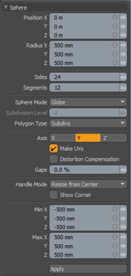
Sphere Properties
When the Sphere tool is active, the following options are available for editing the primitive:
|
Position X, Y, Z |
These three values establish the 3D location for the center of the ball. |
|
Radius X, Y, Z |
These three values are used to establish the dimensions of the sphere. Set to 1m, 1m, 1m (by default), provides us with a 2-meter ball. |
|
Sides |
The sides are the latitudinal edges of the sphere running from top to bottom. By default the primitive ball uses 24 sides. By increasing this value you can increase the number of "cuts" in the ball. This is useful if you plan to deform the ball as these segments act as hinges during deformation operations. This also increases the smoothness of the sphere by adding extra facets. If you plan to apply subdivision surfaces to the mesh, you can use a lower number of segments as the subdivision smooths out the shape. |
|
Segments |
The segments are the longitudinal edges of the sphere running from right to left. By default the primitive ball uses 12 segments. By increasing this value you can increase the number of "cuts" in the ball. This is useful if you plan to deform the ball as these segments act as hinges during deformation operations. It also increases the smoothness of the sphere by adding extra facets. If you plan to apply subdivision surfaces to the mesh, you can use a lower number of segments as the subdivision smooths out the shape. |
|
Sphere Mode |
Options for various Sphere types. • Globe - the default setting creates a ball, with the controls described above. • Quadball - this option creates an SDS sphere made entirely of polygons containing only four vertices (quads). When this option is active the Sides and Segments settings are disabled and the Subdivision Level control activates. Increasing this value adds complexity to the quadball primitive surface. • Tesselated - by default the ball primitive is composed of mostly-quad polygons with some triangles at the poles. Activating the Tesselated flag creates the sphere from all triangles. When this is active the Tesselation Level sets the resolution of the mesh created. Using a tesselated sphere with a high tesselation level creates a more perfect sphere than the default sides and segments, but with many more polygons. Tesselated spheres are not recommended if you plan to use subdivision surfaces. |
|
Subdivision Level |
For the Quadball and Tesselated sphere mode options, the Subdivision Level sets the number of subdivisions, which determines the number of polygons used to define the overall shape. Larger numbers produce more polygons that are rounder with a smoother surface. |
|
Polygon Type |
You can use this option to determine the type of polygons created: • Face - creates standard unsmoothed polygon faces. • Subdivs - creates Subdivision Surface smoothed polygons. • Catmull-Clark - creates Pixar Catmull-Clark smoothed polygons. |
|
Axis |
Defines the major axis direction, most useful for a Globe type sphere, as it controls the direction of the segments along the radius. |
|
Make UVs |
When this button is active a UV map is automatically generated for the geometry created with the tool. This is a very useful option if you plan to UV map the model you are creating from the primitive as it provides a baseline UV map that you can massage later in the modeling process. In many cases this can reduce the amount of work required to map the model. |
| Distortion Compensation |
Adjusts the aspect ratio and related area size of UV polygons to reduce the distortion in the primitives UVs. Use this option when you create a Sphere that does not have equal radius values. By default, the UVs that are generated for the primitive are distorted and displayed in red and blue in the UV viewport of the UV layout. To view distortion, in the UV viewport, click Options... and then enable Show Distortion. Enabling the Distortion Compensation option reducing the distortion automatically and produced cleaner UVs. This feature also works in real-time as you edit the attributes of the primitive before committing to the final values. |
| Gaps | Specifies empty space at the boundary of the UV space or between UV parts. The UV unit is specified using a percentage value. |
|
Handle Mode |
Provides three types of behavior for corner and side tool handles: • Resize from Center - Resizes both sides of the primitive at the center, when dragging a corner or side handle. • Resize - Resizes the shape at the opposite side, when dragging a corner or side handle. • Move All - Moves the primitive instead of resizing. Tip: You can also move the shape by clicking and holding the Ctrl key when in another handle mode. |
|
Show Corner |
When enabled, displays the bounding box corner handles. |
|
Min X, Y, Z/Max X, Y, Z |
You may also define a sphere based on specific X, Y, and Z bounding box locations in 3D space, which can be specified here. This makes it easy to place a sphere on the ground plane, for instance, by making the Min Y value 0 and the Max Y value 1m. |
Tip: The Sphere primitive supports symmetrical creation. When Applying Precision is activated, creating the primitive shape creates an identical version across the specified axis.
Sorry you didn't find this helpful
Why wasn't this helpful? (check all that apply)
Thanks for your feedback.
If you can't find what you're looking for or you have a workflow question, please try Foundry Support.
If you have any thoughts on how we can improve our learning content, please email the Documentation team using the button below.
Thanks for taking time to give us feedback.