Search is based on keyword.
Ex: "Procedures"
Do not search with natural language
Ex: "How do I write a new procedure?"
Automatic Retopology Tool
The Automatic Retopology tool generates a new mesh item from the input surface. The new mesh is produced according to an automatic retopology algorithm, which outputs a clean mesh with good topology that follows the curvature of the input at a density you specify. The density can be controlled by weight maps and the mesh flow can be controlled by sketching guide curves on the surface.
The Automatic Retopology tool converts a mesh into a mesh made of all 3- and 4-point polygons of a uniform size. To determine this polygon size, the tool looks at the number of polygons you requested in the output and divides the surface of the area by that number. As a result, the target polygon number, either as a number or a percent, is approximated. You can also apply a subdivision to the mesh to produce pure quads. For more information about subdivisions, see Surface Tab.
The retopology algorithm detects sharp edges in the input mesh and preserves them by looking for faces that meet at an angle greater than the crease angle you specify. Although the process is automatic, you can guide the results using standard Modo mesh attributes, such as the Retopo density Weight Map, or the Retopo Edge Lock and Retopo Edge Flow edge selection sets. For more information about applying edge lock and flow curves, see Refining Your Geometry Results.
The Automatic Retopology tool is available from the following UI:
• Open the Topology layout, in the Toolbox on the left pane open the Tools sub-tab, and click Automatic Retopology.
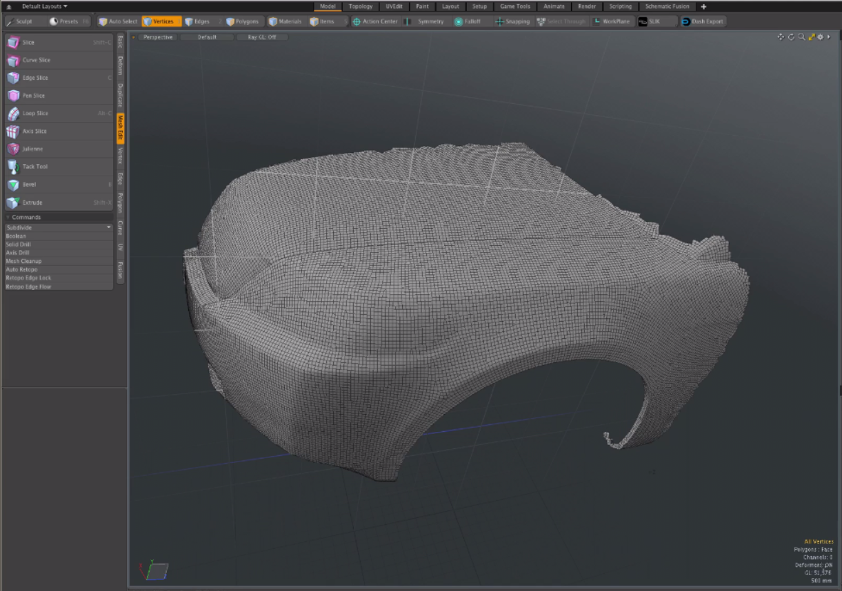
• Open the Model layout, in the Toolbox open the Mesh Edit sub-tab, and click Auto Retopo.
• On the Geometry application menu bar, click Automatic Retopology....
Controlling Results
You can guide the retopology results in three ways:
• by constraining the positions of points,
• by constraining the direction of edges, or
• by changing the relative size of the polygons.
Constraining the Positions of Points by Edge Locking
To constrain positions for points, thus edges in the output mesh, create an edge selection set in the input mesh called Retopo Edge Lock. The retopo algorithm places the points along the edges. You can also apply a position lock by adding a curve to the mesh with the selection set tag Retopo Edge Lock. The curve must also have a vertex normal map with normals that match the surface. You can draw this curve using the Retopo Sketch tool. For more information, see Applying Retopo Guides and Refining Your Geometry Results.
Constraining the Direction of Edges
To constrain directions for edge flows in the output mesh, create an edge selection set in the input mesh called Retopo Edge Flow. The retopo algorithm then aligns the poly flow to the edges. You can also add a flow guide by adding a curve to the scene with the selection set tag Retopo Edge Flow. The curve must also have a vertex normal map with normals that match the surface. You can draw this curve using the Retopo Sketch tool. For more information about vertex maps, see Vertex Normal Maps. For more information about applying curves used to constrain the direction of the edges, see Refining Your Geometry Results.
Changing the Relative Size of the Polygons
A metric is a way of measuring distance on a surface. By defining a different scale at different parts of the mesh, you can warp the uniform polygons to be bigger in some places and smaller in others. This is particularly useful if you want to capture small details in a model without needing a large number of small polygons in the large flat places as well. The smallest polygons are determined by the Relative Polygon Target Count. To get very small detailed polygons, when using a custom metric, you may need to set more than 100% of the polygons in the model. You can get additional control over the metric using the Scale Strength option.
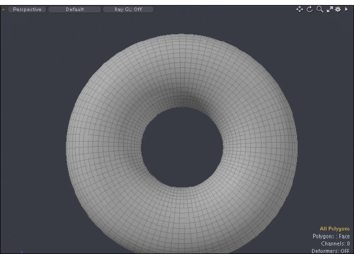
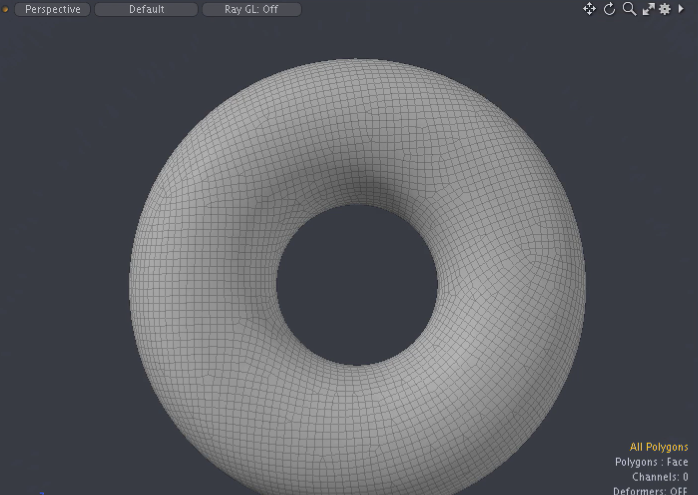
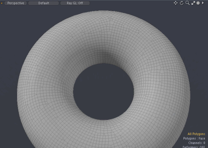
Examples
Click on an image below to enlarge.
|
|
|
|
|
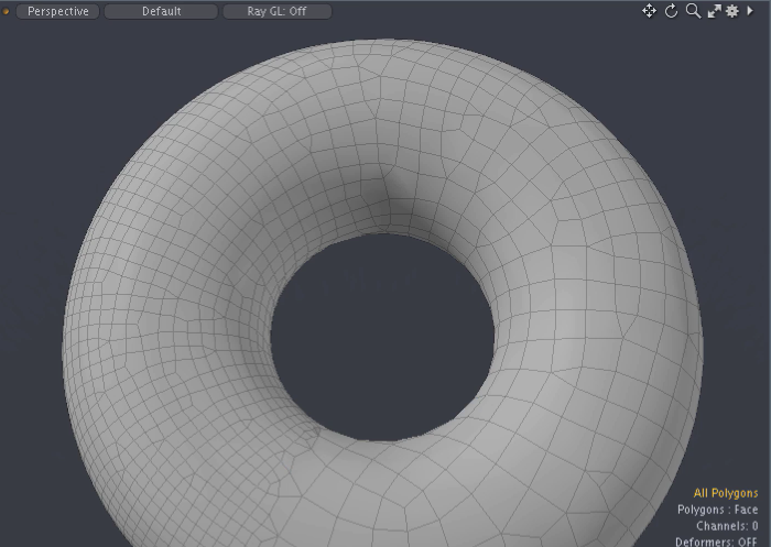
Default Torus |
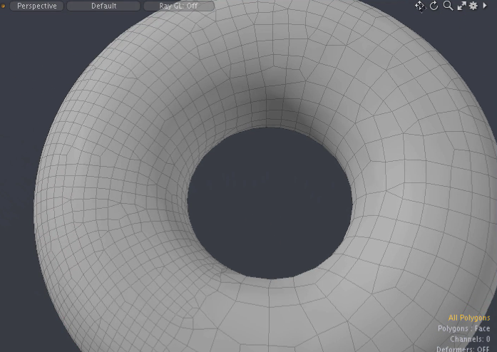
Relative Polygon Target Count 100% |
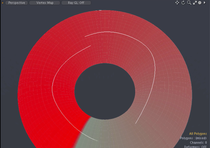
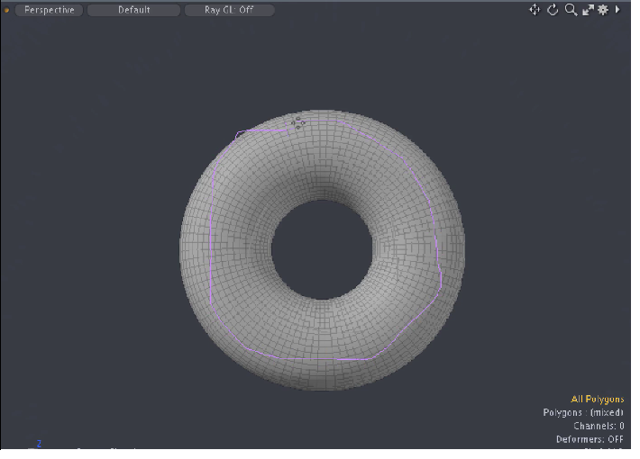
Apply a curve selection for a position lock using Retopo Guides. |
|
|
|
|
|
View Vertex Map - UMap applied. |
Weight Map - UMap applied. |
Weight Map - UMap applied. |
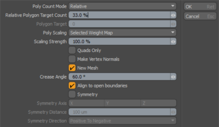
Automatic Retopology Properties
The following options are available:
|
Automatic Retopology |
|
|---|---|
|
Poly Count Mode |
Determines the number of polygons as a percentage of the original mesh, with an absolute number or by adaptively or scaling based on input mesh. The following options are available: • Relative - Scales the existing polygon count set in the Relative Polygon Target Count option to determine the minimum scale of polygons. • Absolute -Determines the minimum scale of polygons. • Adaptive - Attempts to automate the settings for Relative Polygon Target Count and Scaling Strength. It tries to find a high enough mesh density to capture the detail from the smallest edges on the mesh, then computes an appropriate scaling strength for the Shortest Edge metric to scale the lowest density to match the lowest density of the source mesh. Note: When the Adaptive mode is used, the metric argument,Poly Scaling, is disabled but the Relative Polygon Target Count and the Scaling Strength settings can be used to increase or decrease the base density, or to modify the impact of the metric, respectively. |
|
Number of polygons expressed as a percentage of the current polygon count. This number determines the average poly area, which guides the retopology process. Note: This calculation is not exact. |
|
|
Polygon Target |
Number of polygons. If this is not zero, it overrides the Relative Polygon Target Countvalue. This number determines the average polygon area, which guides the retopology process. Note: This calculation is not exact. Tip: Watch out for large polygons next to small polygons. Bump up the Polygon Target count to capture small polygon details. |
|
This option sets the Custom Metric that changes the relative polygon sizes based on a particular mesh attribute. Tip: Use larger Poly Scaling values to create larger polygons in areas where detail is not needed. The following options are available: • Selected Weight Map - Use the currently selected weight map, or if none is selected, a weight map named RetopoDensity is used to control the polygon size. Values from 0 to 1.0 drive the scale of polygons from largest to smallest. For information about weight maps, see Weighting Tools. • Poly Area - This metric scales the output polygon size based on the input polygon size. This is useful on models with small details. • Shortest Edge - This metric is very similar to the Poly Area metric but instead of using the area of the polygons to scale the density, it uses the length of the minimum edge on the polygon. This can make a difference when a mesh has very large and narrow triangles, as is commonly seen in models imported from CAD data. • Curvature - This metric computes the surface curvature and makes polygons larger in flatter areas. It uses the surface curvature at each vertex to scale the density of quads in the retopology result mesh, making the mesh more dense where the mesh is curved and less dense where it is flat. This is intended to capture the shape of the surface more accurately without wasting a lot of polygons in the flat areas. |
|
|
A multiplier to weight the influence the polygon scaling. Amplify the strength of the custom metric by increasing this over 100%. |
|
|
Quads Only |
This option causes the retopology result mesh to be subdivided once to eliminate any 3-point polygons. |
|
Make Vertex Normals |
Enable to generate a vertex map with vertex normals. |
|
New Mesh |
Enable to create a new mesh. |
|
Crease Angle |
The minimum angle that is treated as a sharp crease. Polygons that meet at a sharper angle than this value are assumed to have a sharp edge. |
|
Align to open boundaries |
This option preserves any open boundaries on the mesh and guides the edge flow. |
|
Symmetry |
Turn on this option to perform automatic retopology on only one side of the mesh, then mirror and merge the result. This creates a new mesh that is symmetrical along the selected Symmetry Axis. It also produces results faster. |
|
Symmetry Axis |
Choose the axis of symmetry. |
|
Symmetry Distance |
This option provides a margin of error for the input mesh, in case some of its middle points are over the line. It also sets the merge distance when mirroring the result mesh and merging seam vertices. If your result has gaps along the seam, you may need to increase this number. |
|
Symmetry Direction |
Specifies the direction of the operation. The following options are available: • Positive To Negative: Delete polygons on the negative side and mirror the remaining polygons on the positive side. • Negative To Positive: Delete polygons on the positive side and mirror the remaining polygons on the negative side. |
Applying Auto Retopology
The following is a simple example of applying the Automatic Retopology tool using the Model layout.
| 1. | Open the Model layout, open the Basics sub-tab in the Toolbox, and then add a Torus Primitive to your scene. |
| 2. | Open the Mesh Edit sub-tab in the Toolbox and click Auto Retopo. |
The Auto Retopo dialog is displayed.
| 3. | Change the Automatic Retopology Properties settings and then click OK. |
Retopo Guides
The Retopo Guides tool allows you to sketch curves (polylines) on a surface, which are set up as position and edge flow guides for Automatic Retopology. These curves are tagged with a special selection set name that the autoretopo command looks for and they have a vertex normal map with normals taken from the selected surface. As a result of placing Retopo Guides on your mesh, the curve polygon on the surface creates a polygon selection set, which improves the alignment flow to the curves and to the natural direction of the selected mesh.
Tip: The Retopo Guides tool can also be launched with the command tool.set retopo.sketch on.
Applying Retopo Guides
The following is an example applying curves to constrain directions for edge flows in the output mesh.
| 1. | Open the Topology layout and select a mesh in your scene. |
| 2. | In the Toolbox on the left pane, open the Tools sub-tab, click Automatic Retopology and apply the default setting. |
| 3. | In the Toolbox on the left pane, under the Tools sub-tab, click Retopo Guides. |
| 4. | Click and drag on the surface to defines curves. |
| 5. | In the Toolbox on the left pane, under the Tools sub-tab, click Automatic Retopology. |
| 6. | Click OK to apply the default settings. |
The alignment flow is updated.
Refining Your Geometry Results
To refine your geometry results, to create better tessellation of the polygons on your model, you can set the Automatic Retopology tool to lock to specified sharp edges on your mesh and to curves used to specify the direction of the flow of polygons. The following procedure walks you through the process of using both Retopo Edge Lock and Retopo Edge Flow to apply the edge selection sets to the selected edges.
To refine your geometry results:
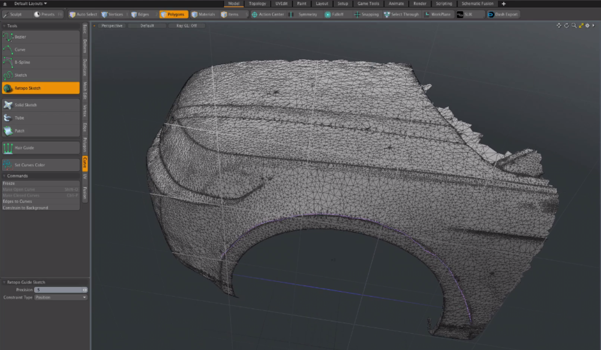
| 1. | In the Model layout, on the Toolbox on the left pane, click the Curve sub-tab. |
| 2. | Click the Retopo Sketch tool and sketch curves onto the geometry of your mesh. |
In this example, curves are drawn on sharp edges.
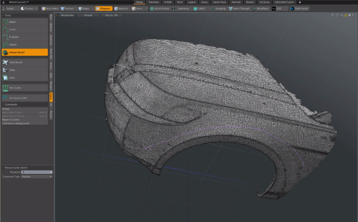
| 3. | Select all of the curves you have created. To quickly do this, open the Mesh Operations List, click the Lists sub-tab in the lower pane. Under the Statistics sub-tab, expand Polygons > By Type and click the + (plus) button beside Curves. All of the curves are now selected. |
| 4. | Set the Auto Retopology tool to lock to edge curves. With the selection of curves activated, click the Mesh Edit sub-tab in the Toolbox, and then click Retopo Edge Lock. |
When using this option, you are using the curves drawn on sharp edges to tell the Auto Retopology tool to calculate a more uniform mesh based on the selected curves.
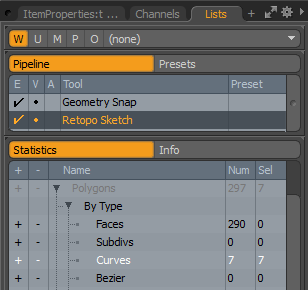
| 5. | Specify the flow direction of the geometry between the locked edges by drawing flow curves onto your mesh. Click the Curves sub-tab in the Toolbox, click Retopo Sketch, and draw your flow curves. |
In this example, directional flow curves are drawn around the wheel fender and the front of the hood.
| 6. | In the Toolbox, click the Mesh Edit sub-tab, and then click Retopo Edge Flow. |
When using this option, you are using the curves drawn to specify the flow direction of the geometry and to tell the Auto Retopology tool to calculate a more uniform mesh based on the selection of curves.
Tip: A selection set is automatically created. To view this selection set, in the Mesh Operations List, under the Statistics sub-tab, expand Polygons > By Selection Set. Depending on the method you have applied, RetopoEdgeLock or RetopoFlow is listed with their respective curve counts.
| 7. | Run the Auto Retopology tool. In the Mesh Edit sub-tab, click Auto Retopo and set the Relative Polygon Target Count percentage or Polygon Target value, and then click OK. In this example, I have set Relative Polygon Target Count to 200%. |
For more information about these options, see Automatic Retopology Properties.
| 8. | To view the results, in the Mesh Operations list, open the Items sub-tab, and click the |
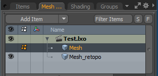
The Mesh_retopo item is displayed in the viewport. Notice the polygon count has been reduced and the tessellation of the geometry has been improved.
Sorry you didn't find this helpful
Why wasn't this helpful? (check all that apply)
Thanks for your feedback.
If you can't find what you're looking for or you have a workflow question, please try Foundry Support.
If you have any thoughts on how we can improve our learning content, please email the Documentation team using the button below.
Thanks for taking time to give us feedback.