Search is based on keyword.
Ex: "Procedures"
Do not search with natural language
Ex: "How do I write a new procedure?"
Vertex Tools
New Vertex
You can create vertices one at a time by specifying their location in 3D space. To do so, choose Geometry > Vertex > Create.
To create an individual vertex:
| 1. | Choose Geometry > Vertex > Create. |
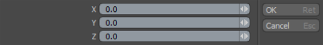
| 2. | In the Create New Vertex dialog, specify the X, Y, and Z coordinates for the vertex's location. |
| 3. | Click OK. |
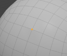
The vertex is visible in the 3D model view.
Set Position
With the Set Position command you can reposition an existing vertex (or many) to a specific position by typing new coordinates. For example, you can center an entire loop of vertices on the zero position for a mirror operation.
| 1. | Select the vertices to change. |
| 2. | In the Toolbar on the left panel, go to the Vertex tab, and under Commands, click Set Position.... |
The command is also available in the menu bar, under Geometry > Vertex.
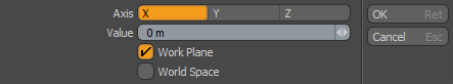
| 3. | Select the Axis along which you want to move your vertices, and specify the Value. |
To assign the position value based off the World Space or the Work Plane position, check the appropriate property.
| 4. | Click OK. |
The selected vertices are set to the new position.
Procedural Vertex Set Position
Set Position is also available as a mesh operation. It works the same way as its direct modeling equivalent.
Tip: For more information on procedural modeling and mesh operations, see Procedural Modeling.
| 1. | Select the vertices to modify. |
| 2. | In the Mesh Ops tab, click Add Operator. |
Tip: If the Mesh Ops tab is not visible on the right panel, click the + button on the right of the tab names, and select New Tab > Data Lists > Mesh Ops.
| 3. | Under Mesh Operations > Vertex, double-click Vertex Set Position. |
You can also find it in the Mesh Operations list.
| 4. | Select the Vertex Set Positon mesh operation in the Mesh Operations list. Its Properties appear in the lower-right panel. |
| 5. | Enable the axes you want to move the vertices along by checking Enable X, Y, or Z and set the Position for the relevant axes. |
The selected vertices are set to the new position.
Align
With the Align command you can align a selection of vertices into a straight row (in a line between the first and last vertices selected).
|
Option |
Description |
|
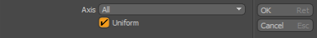
Axis |
Confines the movement of the repositioned vertices to one or All axes. You can also select an axial plane (XY, YZ, or ZX). |
|
Uniform |
When enabled, spaces the vertices evenly (uniformly) along the span. |
Join
The Join command welds the selected vertices to the last vertex selected and then moves them all to the position of the last selected vertex.
You access the Join command on the Vertex tab of the Modo Tools toolbar.
|
Option |
Description |
|
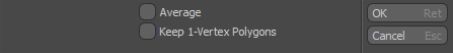
Average |
When enabled, welds the selected vertices into a single vertex positioned at an average distance between the selected points. |
|
Keep 1-Vertex Polygons |
When enabled, allows single vertices to exist after the join operation. When disabled, Modo automatically deletes 1-vertex polygons. |
Join Averaged
The Join Average command welds two (or more) vertices together at a central position between the two vertices.
To join multiple vertices:
| 1. | Select the vertices to join together. |
| 2. | On the Modo Tools toolbar, click the Vertex tab. |
| 3. | In the Commands section, click Join Averaged. |
| 4. | In the Join Vertices dialog, read the message indicating how many vertices were joined into one. |
| 5. | Click OK. |
Remove
The Geometry Remove command deletes the selected vertices, edges, or polygons from the 3D model view.
You can use the Remove command from the Vertex or Edges tab of the Modo Tools toolbar or choose Geometry > Remove. Also, you can use the Backspace or Delete key to remove vertices, edges, or polygons. Geometry Remove works on individual or multiple selected vertices, edges, or vertices.
Collapse
The Collapse command removes the selected element without destroying the integrity of the geometry. You can delete any selected polygon, edge, or vertex but, with this command, no hole is left behind. Instead, Modo heals the mesh to close any gaps by merging neighboring elements together.
You access the Collapse command in several places:
• Vertex: On the Vertex tab of the Modo Tools toolbar click Commands > Collapse.
• Edge: On the Edge tab of the Modo Tools toolbar click Commands > Collapse Edges.
• Polygons: On the Polygons tab of the Modo Tools toolbar click Commands > Reduce > Collapse.
• You can also select whatever geometry to collapse and then choose Geometry > Collapse.
Split
The Split command for vertices is the opposite of the Join command. Instead of combining multiple vertices into a single vertex, this command takes a single vertex and creates multiple vertices in the same location based on the number of polygons that share the point.
To use the tool:
| 1. | Select the vertices to split. |
| 2. | In the Toolbar on the left panel, go to the Vertex tab, and under Commands, click Split. |
The command is also available in the menu bar, under Geometry > Vertex.
Unlike the Join command, Split creates the multiple vertices in their original location, it doesn't move them apart. Select any polygon or edge and move it to separate the split vertices.
|
|
|
|
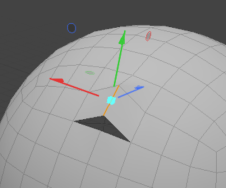
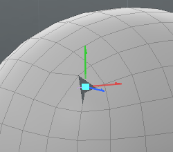
The vertices after applying Split. |
Moving an edge reveals that the vertices are split. |
Procedural Vertex Split
Vertex Split is also available as a mesh operation. It works the same as its direct modeling equivalent.
Tip: For more information on procedural modeling and mesh operations, see Procedural Modeling.
| 1. | Select a vertex to split. |
| 2. | In the Mesh Ops tab, click Add Operator. |
Tip: If the Mesh Ops tab is not visible on the right panel, click the + button on the right of the tab names, and select Data Lists > Mesh Ops.
| 3. | Under Mesh Operations > Vertex, double-click Vertex Split. |
The mesh operation is applied to your geometry and you can also find it in the Mesh Operations list. If you then move a connected edge or polygon, the split vertices are revealed. The following example shows the Edge Slide mesh operation applied to a connected edge.
Merge
The Merge Vertices command measures the distance between vertices in the currently selected geometry to see if any fall within a specific distance threshold to one another. If any vertices are within that range, Modo combines them into a single vertex. It positions the resulting vertex at the site of the most recently selected vertex of the merged vertices.
The Merge command is on the Vertex tab of the Modo Tools toolbar in the Tools section. The following options are available:
|
Option |
Description |
|
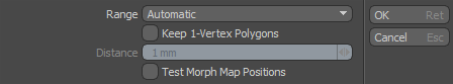
Range |
Specifies when to merge vertices. By default, the Merge Vertices command uses a Range setting of Automatic. • Automatic: Merges only vertices that share the exact location on all three axes. • Fixed: Provides a way to specify a distance threshold. Select to increase the distance allowed between two vertices to be merged. After selecting Fixed, you can set a threshold value for the Distance. |
|
Keep 1-Vertex Polygons |
When enabled, leaves behind any 1-vertex polygons from merging vertices. Often when merging vertices within a certain threshold, polygons become flattened into only one vertex. In this case they become 1-vertex polygons. These 1-vertex polygons can cause rendering anomalies and other issues in the model file when exporting to other systems. When disabled (by default), Modo removes these 1-vertex polygons. However, there are some cases where you may want to keep the resulting 1-vertex polygons. |
|
Distance |
Specifies the distance threshold if you selected Fixed as the Range. For example, if the Distance is set to one meter, Modo merges any points that fall within one meter of another point. |
|
Merge Discontinuous UV Values |
Enabled by default, merges discontinuous UV values together into continuous data to optimize the UV map. |
Sorry you didn't find this helpful
Why wasn't this helpful? (check all that apply)
Thanks for your feedback.
If you can't find what you're looking for or you have a workflow question, please try Foundry Support.
If you have any thoughts on how we can improve our learning content, please email the Documentation team using the button below.
Thanks for taking time to give us feedback.