Search is based on keyword.
Ex: "Procedures"
Do not search with natural language
Ex: "How do I write a new procedure?"
Deferred Meshes
In complex or geometrically-dense scenes the Deferred Mesh option works to convert an existing non-deforming mesh to an externally saved .lxdf file. This action removes the geometry from the scene, while remaining as a renderable element. The main benefits to using deferred meshes are a reduced memory footprint, better scene interactivity, and faster scene save times.
Memory is reduced because the element, when saved out to the .lxdf format, is diced up into multiple segments. At render time, only the required segments are loaded, allowing for the rendering of massive data sets. Scene interactivity is also greatly improved because the overhead required to edit the dense mesh is eliminated and the scene saving happens much more quickly, as the element doesn't need to be written to disc during each save operation (especially beneficial to the Autosave function).
The Deferred Mesh option appears functionally similar to a Render Proxy mesh, as both save Mesh Items to external files, but the Deferred Mesh has some important differences. The main one being that a Deferred Mesh is not user-editable. When the item layer is saved as a .lxdf, the mesh itself is essentially frozen and triangulated whereas a Render Proxy mesh is saved as a regular .lxo file that can be opened separately, edited, and updated. Another difference is that the shading of the Deferred Mesh remains in the original scene. Only the geometric data is stored externally. For Render Proxies, the shading definitions are moved into the .lxo file along with the geometry.
Converting Meshes
Any regular non-deforming mesh layer or static mesh layer can be converted to a Deferred Mesh. This means that the target mesh can be animated to move, rotate, or scale, but it must remain rigid in overall shape. For example, if a Bend Deformer were applied to the mesh, when converted to the Deferred Mesh, the bending deformation would be ignored.
Conversion to the Deferred Mesh is done in the Item List contextual menu.
| 1. | With the layer selected, right-click over the layer to open the menu and select Change Type > Procedural > Deferred Mesh. |
This action opens an OS-dialog, asking you where to save the resulting .lxdf file.
| 2. | Define a name and press OK to convert to the Deferred Mesh. |
This action freezes the mesh into triangles and converts the mesh. If any Subdivision Surfaces are present, the Render Level subdivision value is applied during the Freeze process.
Once completed, the Mesh Item is replaced in the Item List by the same named Deferred Mesh item. You can select the item and adjust its attributes in the Properties panel.
Warning: If you want to further edit a model that is converted to a Deferred Mesh, a separate version should be saved beforehand. Once a mesh has been converted to a Deferred Mesh and the scene file has been saved and closed (the undo stack is deleted), there is no way to return to the original unconverted version of the mesh.
Adding Meshes
Once a Deferred Mesh is created it is possible to add additional Mesh Items to the existing .lxdf file. To do this, follow these steps:
| 1. | Select both the Deferred Mesh item layer in the Item List and the target mesh(es) to convert. |
| 2. | Then under the Deferred Mesh sub-tab of the Properties panel, select the Add Geometry button. |
This opens the Add Deferred Geometry dialog (items contained within a Deferred Mesh are individually referred to as Surfaces).
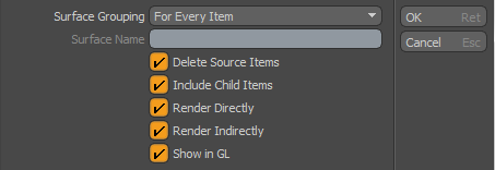
This dialog allows you to define how the new geometry is added by its Surface Grouping setting and how it displays with its default display settings:
• Surface Grouping - defines how the additional item are treated within the Deferred Mesh file, once converted. Defining the proper Surface Grouping is important because it controls how the mesh can be affected in the future. There are three possible options:
• For Every Item defines a separate grouping for every individual item that is added.
• For Selected Root Items merges entire hierarchies of items into individual surface groups, named by their root item.
• One Surface merges all items into a single surface group, named by the Surface Name input field. Defined Groups can be selected within the Deferred Mesh using the Current Surface pop-up in the Properties panel.
Note: Once combined as such, there is no way to undo the action or to then split individual surfaces out from the Deferred Mesh.
• Surface Name - when set to One Surface, this input field defines the name for the generated surface.
• Delete Source Items - when enabled, removes the item layers from the source scene, once they are converted.
• Include Child Items - when enabled, automatically includes all child items for selected root items.
• Render Directly/Render Indirectly - rendering of deferred surfaces can be split into two distinct passes, Direct and Indirect. Direct refers to light that is evaluated from direct light sources in the scene, such as a Spot Light or a Distant light. Indirect refers to global illumination rendering. This is the bounced light in the scene producing the color bleeding that happens between two surfaces. The reason for this distinction is that separate geometry can be used for each lighting pass. One high resolution surface for the direct rendering, and another lower resolution surface for the bounced global illumination rendering. When set-up as such, this method of rendering can increase the performance of capturing indirect illumination as detailed surfaces tend to slow down the evaluation of the bounced light. Once the mesh surfaces have been properly defined, the Indirect LOD option must also be enabled in the Render Item at the very bottom of the Settings sub-tab.
• Show in GL - controls visibility of the Deferred Mesh in the GL viewports. When enabled, the resulting Deferred Meshes are visible in the 3D viewport. When disabled, the Deferred Mesh shows up as an empty bounding box.
Note: When the Surface Display is set to Direct Surfaces as Boxes, the GL display is controlled by the Render Directly toggle, and not Show in GL. This is because the boxes shown are based on the render time geometry, so turning off render time geometry means that no boxes are created.
Removing Meshes
Removing of items stored in a Deferred Mesh .lxdf file can be done by selecting the target surface to be removed using the Current Surface option. Once selected, press the Remove Surface button. This opens the Remove Deferred Surfaces dialog:
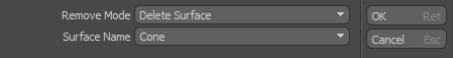
• Remove Mode - controls what action is performed on the selected surface:
• Delete Surface - removes the surface definition from the Deferred Mesh files. (This action is not undoable.)
• Extract to Static Mesh - extracts the surface definition and places it in a Static Mesh Item. (This action is not undoable.)
• Split to Independent Surface - extracts surface definition to a Deferred Surface item that can be controlled independently (see Independent Surfaces below).
• Surface Name- allows you to select alternate surfaces for removal if the initial selection was incorrect.
Independent Surfaces
If a Deferred Mesh contains multiple surfaces, there may be cases where you want to break out individual surfaces so they can be either animated, shaded, or their visibility adjusted independently (or all three). This is done by creating a Deferred Surface. A Deferred Surface is an independent item in the scene, but it is still contained within its original Deferred Mesh .lxdf file. To create a Deferred Surface select the surface from the Current Surface pop-up. Once selected press the Remove Surface button. This opens the Remove Deferred Surfaces dialog (explained above). Select the Split to Independent Surfaces option to convert the selection to a Deferred Surface.
Deferred Mesh Tab Properties
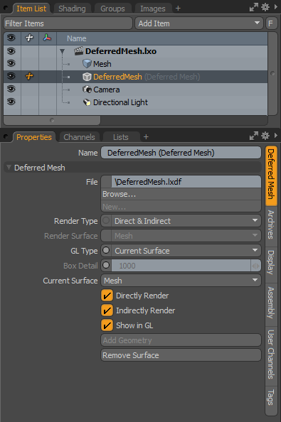
The following Deferred Mesh options are available for Deferred Mesh:
• File - lists the name and location on disc of the saved .lxdf deferred mesh file. The Browse option can be used to locate an alternate file as a replacement to the current file. The New option triggers the saving of a new Deferred Mesh file when an additional mesh layer is also selected.
• Render Type - determines the rendering evaluation of the contents of the deferred mesh:
• Direct & Indirect - any surface with either the Direct Rendering toggle or the Indirect Rendering toggle is evaluated directly or indirectly, according to its setting. This is the default and probably most common choice.
• Direct Only - only surfaces with the Direct Rendering toggle enabled render.
• Indirect Only - only surfaces with the Indirect Rendering toggle enabled render.
• One Surface - only a single named surface from within the Deferred Mesh renders, defined by the Render Surface option below.
• Render Surface - defines the surface that renders when the Render Type is set to One Surface.
• GL Type - determines how the contents of the Deferred Mesh file are displayed in the 3D viewport:
• None - shows no surfaces in GL.
• Current Surface - shows only the surface matching the name in the Current Surface channel.
• All GL Surfaces - shows all the surfaces with the Show in GL toggle enabled.
• All Indirect Surfaces - shows all the surfaces with the Indirect Rendering toggle enabled.
• Direct Surfaces as Boxes - shows all surfaces with the Direct Rendering toggle enabled using a variable bounding box representation.
• Box Detail - defines an upper limit to the number of boxes used when the Direct Surfaces as Boxes option is set.
• Current Surface - allows you to select separate surface from within the Deferred Mesh file (added separately). Displayed surfaces can be modified for remove and to separate it out as a different surface using the other controls within the Properties panel.
• Directly/Indirectly Render - defines how the deferred surface is rendered. This evaluation can be split into two distinct passes: Direct and Indirect. Direct refers to light that is evaluated from direct light sources in the scene, such as a Spot Light or a Distant light. Indirect refers to global illumination rendering. This is the bounced light in the scene producing the color bleeding that happens between two surfaces. The reason for this distinction is that separate geometry can be used for each lighting pass; one high resolution surface for the direct rendering, and another lower resolution surface for the bounced global illumination rendering. When set up as such, this method of rendering can increase the performance of capturing indirect illumination as detailed surfaces can tend to slow down the evaluation of the bounced light. Once the mesh surfaces have been properly defined, the Indirect LOD option must also be enabled in the Render Item at the very bottom of the Settings sub-tab.
• Show in GL - controls visibility of the Deferred Mesh in the GL viewports. When enabled the resulting Deferred Meshes are visible in the 3D viewport. When disabled the Deferred Mesh shows up as an empty bounding box.
Note: When the Surface Display is set to Direct Surfaces as Boxes, the GL display is controlled by the Render Directly toggle, and not Show in GL. This is because the boxes shown are based on the render time geometry, so turning off render time geometry means that no boxes are created.
• Add Geometry - used to add additional item to an existing Deferred Surface. See Adding Meshes for more information.
• Remove Surface - used to remove a surface from a Deferred Mesh file or break it out into its own item layer, called a deferred surface. See Removing Meshes for more information.
Archive Tab Properties
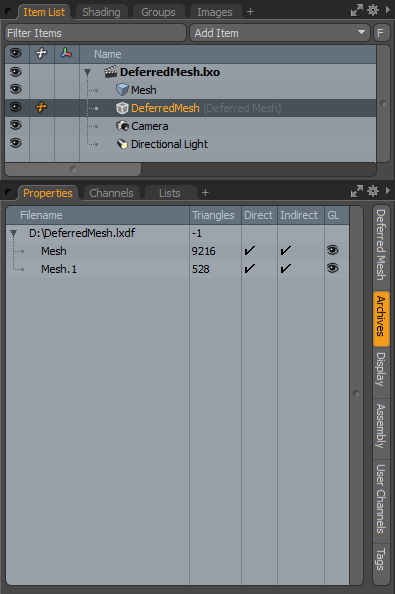
• Archives - displays all the separate surfaces contained within the current Deferred Mesh. You can view the surfaces and their polygon count statistics as well as the settings for the rendering and visibility toggles all at one time.
Deferred Surface Tab Options
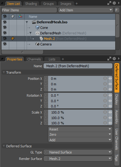
• Name - displays the current item name. You can easily change it by clicking within the field and typing the new name.
The following Transform options are available for the Deferred Surface:
• Position - an item transform that allows you to numerically position the item in XYZ space. By default, Position transforms originate from the item's Center position.
• Rotation - an item transform that allows you to numerically set the rotation of the item. By default, Rotation transforms originate from the item's Center position.
• Scale - an item transform that allows you to numerically set the size of the item. By default, Scale transforms originate from the item's Center position.
• Freeze - returns the item's Center position to the world space center (0,0,0) without changing the position of the Mesh Item itself.
• Zero - resets the chosen transform property values to 0, leaving the Center position and mesh position intact. This is done by adding an additional transform item to the Mesh Item's channels with an inverted version of the current values. This is useful to allow, for example, a joint to have a base value of 0,0,0 but still be located away from the World Origin.
• Add - adds additional Transform items to the associated item, or if they do not yet exist it simply adds them. Transform items are the channel groups that store the actual transform values controlling any item's position, rotation, and/or scale. You can add as many transform items as desired for any transform property desired. Adding additional Transform items produces an additive effect, where each transform group is evaluated before the next and so on. Additional item transforms are evaluated in their order in the channels list, from the bottom upwards.
It should be noted that, by default, new items do not have any transform items associated with them (even though they are visible here within the Properties panel). This is useful as an optimization as only the necessary transforms are created on an as-needed basis, reducing scene overhead. There are several actions that add these base transform items. One is by simply transforming the target item with one of the various transform tools or by editing the values' input fields. This action causes the particular transform item to be added automatically to the Channels viewport list. Due to this fact, you may need to specifically create item transforms when Referencing, because in order to override the channels in the Master scene, they must first exist.
The following Deferred Surface options are available for the Deferred Surface:
• GL Type - determines how the contents of the Deferred Mesh file are displayed in the 3D viewport:
• None - shows no surfaces in GL viewport, just a bounding box.
• Named Surface - shows only the surface matching the name in the Render Surface channel.
• Named Surface as Boxes - shows the Render Surface definition using a variable bounding box representation.
• Render Surface - sets the Render Surface for either of the named surface options.
Sorry you didn't find this helpful
Why wasn't this helpful? (check all that apply)
Thanks for your feedback.
If you can't find what you're looking for or you have a workflow question, please try Foundry Support.
If you have any thoughts on how we can improve our learning content, please email the Documentation team using the button below.
Thanks for taking time to give us feedback.