Search is based on keyword.
Ex: "Procedures"
Do not search with natural language
Ex: "How do I write a new procedure?"
Dynamic Item
To make an item dynamic, you need to tag it with one of the dynamic item types. Each type determines how the body behaves when moving or colliding with other objects. For example, a Soft Body bends and deforms similar to cloth, whereas a Rigid Body doesn't deform or break. The different types of dynamic item are described in Dynamic Item Types.
Dynamics are created in the Setup layout.
To Make an Item Dynamic
| 1. | Select the Setup layout and go into Items mode. |
| 2. | Select the item. |
| 3. | Click the Dynamics sub-tab of the Commands panel on the left. |
This opens the Dynamics toolbox.
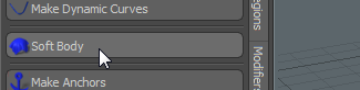
| 4. | Select the type of dynamic item that you want to apply. |
This tags the selected item with the dynamic item type.
For example, to apply soft, cloth-like dynamics, select Soft Body.
To Remove Dynamics from an Item
To stop an object having dynamic properties:
| 1. | In Items mode, select the item. |
| 2. | Select Dynamics > Remove Dynamics. |
OR
Hold Shift. You'll see that most of the dynamic item buttons change to Remove Dynamics.
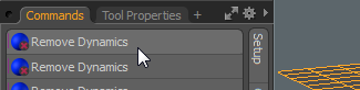
Click any of the Remove Dynamics buttons.
To Toggle Dynamics on an Item
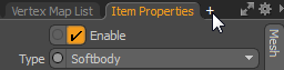
To temporarily disable an item's dynamics, uncheck Enable at the top of the Dynamic tab in the Item Properties panel.
Dynamic Item Properties
A dynamic item has an additional property tab called Dynamic in the Item Properties panel. The Dynamic tab contains the settings for the dynamics simulation.
You can modify the settings to change the behavior of the dynamic item during movement and collision. When a dynamic item is selected, the following attributes appear in the Properties panel.
General Properties
|
General Properties |
|
|---|---|
|
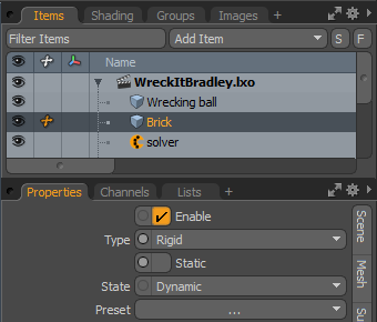
Enable |
Toggles dynamics on and off for the item. When enabled, Modo applies dynamics to the item when a simulation is run or cached. When disabled, the dynamic properties are ignored. |
|
Type |
Dynamic items can be defined as one of three types: • Rigid: The item is treated as a solid object with a fixed, unchanging volume. • Softbody: A soft body deforms during a collision or when a force is applied. • Curves: Curves are used for items that consist of one or more curved strands, such as hair or wires. Selecting each option hides/reveals different attributes in the Properties panel. |
|
Static |
The associated item does not move during a simulation (even if animated), acting strictly as a collision object. When Static is disabled, two options become available in State. |
|
State |
State is enabled when an item is not static. • Dynamic: These are collision items controlled exclusively by dynamics. They can also be affected by constraints, forces, and falloffs. This is automatically assigned when an object is defined as an Active Rigid Body. Note: This should be set for animating fur guides. • Kinematic: An animated collision object that is controlled by keyframe information. Kinematic objects are unaffected by forces, such as gravity or falloffs. This is automatically assigned when an object is defined as a Kinematic Rigid Body. |
|
Preset |
Modo offers a series of presets to determine the dynamic properties of an item. If you select a preset, the values are automatically adjusted, and the item takes on the physical properties of the chosen material. You can choose from Glass, Stone, Wood, Plastic, or Steel. |
Collision: Rigid
|
Collision: Rigid |
|
|
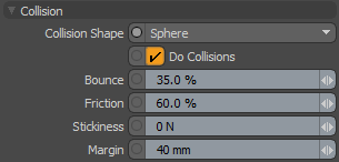
Collision Shape |
This is the shape to calculate collision contacts between dynamic objects. In general, you should choose the simplest shape that produces satisfactory results. The default collision shape is set to Hull, which generally balances accuracy with calculation speed. • Box: A rectangular box defined by the bounding box of the geometry's maximum extents. • Sphere: A sphere that is sized to encompass all the geometry of the object. • Hull: This collision shape creates the smallest convex volume that encompasses all the points in this mesh (imagine the mesh enveloped in shrink-wrap). The Hull collision type does not support holes or indentations in the object. Although it only approximates the item's shape, it provides very fast collision detection on complex shaped objects. • Multi Hull: The default collision option, Multi Hull generates a separate convex hull for each polygon island in the mesh. These are then treated as a single, compound dynamic item. • Mesh: Uses the mesh of the object for calculating collisions. For subdivision surface models, the actual frozen Sub-D cage is used. Note: Avoid this option on Dynamic Rigid Bodies (it is fine for Static and Kinematic ones). Otherwise, performance and simulation stability can suffer negatively. • Convex Decomposition: Creates multiple hulls (see above) and connects them together. This works to better approximate the actual shape of the geometry, but can be costly to initially compute with complex shapes. • Plane: Generates an infinite ground plane collision shape, originating from the center of the associated geometry's bounding box (not on the item's actual center position). |
|
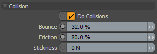
Do Collisions |
Disable this option to remove the object from collision calculations. |
|
Bounce |
This is the collision response when the object hits another dynamic object. A value of 0% means the object doesn't bounce or inherit energy from the other dynamic object. A value of 100% means the object inherits all of the energy from the contact object. Values above 100% produce rubber ball-like effects where objects impart more energy from contacts. |
|
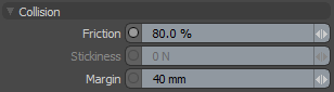
Friction |
The amount an object slides against another object. A value of 0 offers no resistance. A value of 1 stops the object from sliding. |
|
Stickiness |
When two dynamic elements collide and they both have a non-zero Stickiness, they attach to each other at the collision point. The higher the Stickiness value, the stronger the bond between the elements. Lower values allow stuck elements to be broken more easily. |
|
Margin |
This value helps the bullet engine to better determine collisions and improves its performance and reliability. It defines a gap around the object used to detect a collision contact. In most cases it should be kept at its default value. When used with the Mesh and Convex Decomposition settings, this can offset items away from each other, so only a small amount is necessary. Note: A setting of 0 may produce errors in collision detection. |
Collision: Softbody
|
Collision: Softbody |
|
|---|---|
|
Friction |
The amount that a soft body slides against another dynamic object. A value of 0 offers no resistance. A value of 1 stops the object from sliding. |
|
Stickiness |
When two dynamic elements collide and they both have a non-zero Stickiness, they attach to each other at the collision point. The higher the Stickiness value, the stronger the bond between the elements. |
|
Margin |
This value helps the bullet engine to better determine collisions and improves its performance and reliability. It defines a gap around the object used to detect a collision contact. Note: A setting of 0 may produce errors in collision detection. |
Collision: Curves
|
Collision Curves |
|
|---|---|
|
Do Collisions |
Disable this option to remove the object from collision calculations (enabled by default). |
|
Bounce |
This is the collision response when the curve capsule colliders hit another dynamic object. A value of 0% means the object doesn't bounce or inherit energy from the other dynamic object. A value of 100% means the object inherits all of the energy from the contact object. Values above 100% produce rubber ball-like effects where objects impart more energy from contacts. |
|
Friction |
The amount an object slides against another object. A value of 0 offers no resistance. A value of 1 stops the object from sliding. |
|
Stickiness |
When two dynamic elements collide and they both have a non-zero Stickiness, they attach to each other at the collision point. The higher the Stickiness value, the stronger the bond between the elements. |
Mass
|
Mass |
|
|---|---|
|
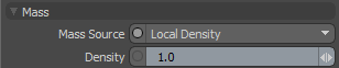
Mass Source |
• World Density: Calculate the mass by multiplying the calculated volume of the dynamic item by the Global Density value defined on the Dynamics Solver item. • Local Density: Mass is calculated by multiplying the computed volume by this value. • Local Mass: Set the mass manually. |
|
Density |
The measure of the amount of matter in any given volume. If the Mass Source option is set to Local Density, this value is used to calculate the mass. |
|
Mass |
The property of an object that gives it bulk and weight. If Mass Source is set to Local Mass, this value is used for simulations. |
Sleep
Note: Sleep is only available for Rigid Body items.
Normally, objects are awake (active) when any dynamic simulation starts and the object begins to react immediately. You can change this behavior, delaying when individual objects wake up and become active, essentially controlling when items begin their participation in a simulation.
|
Sleep |
|
|---|---|
|
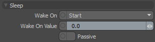
Wake On |
Before the Wake On event, items can be keyframe-animated and the object is handed off to dynamics for simulation when the Wake On Value threshold is reached. The values defined in the Impulse channels are applied when the object wakes up. • Start: The object begins the dynamic simulation awake and fully active at the beginning of the scene. • Collision Velocity: The object wakes up when it collides with a passive or active object. • Collision Force: The object wakes up when it collides with a passive or dynamic object. • Velocity: The object wakes up when a certain velocity is reached. Different from Collision Velocity, this velocity is determined by keyframe animated motion. • Trigger: The object wakes up when the keyframe-able channel, reWakeOnValue, is not zero. This has good use with conditional nodes in rigging. • Frame: The object wakes up when a specific frame number is reached. • Time: The object wakes up when a specific time has been reached, regardless of frame rate. • Force: The object wakes up when the force applied by a force item reaches the threshold. Note: Use the Wake On Value to set a threshold for the Collision Velocity, Collision Force, Velocity, or Force. |
|
Wake On Value |
This is the threshold that must be reached in order to wake up the object, depending on the Wake On option selected. |
|
Passive |
When enabled, sleeping objects react to collision forces only. This means they can be pushed around but stop moving the moment the influence stops. |
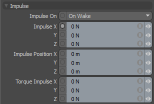
Impulse
Note: Impulse is only available for Rigid Body items.
|
Impulse |
|
|---|---|
|
Impulse On |
This option determines the state that causes the Impulse value to be applied to the dynamic item. • Off: No impulse value is applied to the object. • On Wake: The impulse values are applied when the item wakes up, as determined by the Sleep settings. • Continuous: The impulse value is applied to the object continually at every step in the evaluation. |
|
Impulse X/Y/Z |
A directional force that is applied to the object when it wakes up. This is useful when a keyframed object is handed off to dynamics, imparting direction and velocity to the object. Without Impulse the velocity would drop, as dynamics has no awareness of the object's velocity prior to waking up. |
|
Impulse Position X/Y/Z |
The position the Impulse is applied from, affecting the object's trajectory. |
|
Torque Impulse X/Y/Z |
A rotational force that is applied to the object when it wakes up. This is useful when a keyframed object is handed off to dynamics, imparting rotation to the object. Without Torque Impulse the object would not spin, as dynamics has no awareness of the object's motion prior to waking up. |
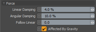
Force
|
Force |
|
|---|---|
|
Linear Damping |
This is a force that acts upon the motion of objects to slow them down over time. A small value here can benefit object stability, since it helps objects come to rest. |
|
Angular Damping |
Same as Linear Damping, but applies to the rotation of the object. Note: Angular Damping is not available for Soft Body objects. |
|
Follow Linear |
When under the influence of the dynamics system, animated dynamic items ignore their user-assigned kinematic (keyframed) motion. Instead, they act under the forces applied to them, and any collisions encountered. Follow Linear applies an amount of force to an item to seek its kinematic position. The setting allows you to influence a dynamic solution by adding keyframes to the item and increasing the Follow Linear force value. |
|
Affected by Gravity |
Turns gravity on or off for the object. |
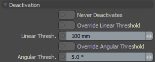
Deactivation
Note: Deactivation is not available for Soft Body items.
|
Deactivation |
|
|---|---|
|
Never Deactivates |
When enabled, the item never gets deactivated due to no motion. When disabled, the item is disabled when it meets the defined linear and angular thresholds defined in the solver item (or overridden here). |
|
Override Linear Threshold |
Enable this function to put dynamic objects to sleep once they reach a defined upper threshold value, overriding the global value found in the Dynamics Solver. This behaves opposite to the Wake On settings; once an object has been below the threshold for the defined length of time, it is put to sleep. |
|
Linear Threshold |
The motion threshold value when Override Linear Threshold is enabled. |
|
Override Angular Threshold |
Enable this function to put dynamic objects to sleep once they reach a defined upper threshold value, overriding the global value found in the Dynamics Solver. This behaves opposite to the Wake On settings; once an object has been below the threshold for the defined length of time, it is put to sleep. |
|
Angular Threshold |
The rotation threshold value when Override Angular Threshold is enabled. |
Particles

|
Particles |
|
|---|---|
|
Particle Collision Roughness |
This adds a random factor to the direction in which particles bounce off the item. At 100% it can bounce up to 90 degrees away from the collision normal. |
|
Particle Collision Stickiness |
The distance at which particles try to stick to the surface of an item. |
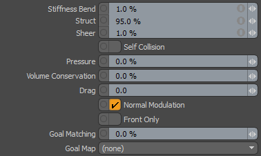
Soft Body
|
Soft Body |
|
|---|---|
|
Stiffness Bend |
The shape of a Soft Body is determined by virtual springs, evaluated between the vertices in the mesh. These springs help an object maintain its shape by applying a rotational force to maintain the continuity of the surface. Stiffness can be reduced all the way to 0, creating a very soft and saggy fabric type. |
|
Struct |
These springs follow along the lines of the mesh (along the polygon edges). This value determines how resistant the springs are to the applied forces when deforming, due to forces such as gravity or turbulence. |
|
Sheer |
These springs are generated to add extra connections to the inside of a polygon face (quad polygons forming an x shape). They help to prevent the polygon from collapsing in on itself. |
|
Self Collision |
Enable this option to fix issues with the surface intersecting itself. |
|
Pressure |
This exerts a force upon the overall volume of an item, similar to how pressure reacts on an object in the real world. Increasing values add overall volume, inflating the item. Decreasing (negative) values reduce its volume, deflating the item. Note: This option requires that the target mesh be completely watertight (no seams). |
|
Volume Conservation |
This option works with the Pressure option. You can use it to preserve the volume of the Soft Body. For example, if you crush one part of a balloon, the rest of it expands so that it still contains the same volume of air. |
|
Drag |
Determines the loss of energy on a surface that is in motion (say, for jiggling-type of effects). |
|
Normal Modulation |
This option multiplies the force applied by the surface normal. |
|
Front Only |
When enabled, forces coming from the back-side of a single-sided object are not applied. |
|
Goal Matching |
If a goal map is specified, this option acts as a multiplier on the map values. |
|
Goal Map |
A Vertex Map that applies to soft body items and controls how much they retain their original shape. It can also be looked at as a stiffness control. In this case, a Weight Map is used. Weight Map values of 1 retain the original position, while values lower than 1 apply an appropriate spring force attempting to retain the initial shape. |
Note: If settings in the Solver and Soft Body properties cause the simulation to become unstable, the Soft Bodies responsible are removed from the simulation. When this happens, the event is reported to the Event log (System > Advanced > Event Log). For more information in the Solver Item, see Dynamics Solver.
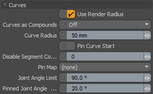
Curves
You can apply simulations to various curve types in Modo, using either Splines or Polylines (fur guides).
The simulations of curves are very much like rigid body calculations, simulating a connected string of rigid capsule shapes drawn between each vertex. Each shape's size is based on the curve radius value in the Mesh Item properties. The resulting capsule collision shapes have three possible states for dynamics: Static, Dynamic, or Kinematic.
|
Curves |
|
|---|---|
|
Use Render Radius |
When enabled, the resulting capsules generated with dynamics, match the size defined, even when they are modulated with a curve width gradient. |
|
Curves as Compounds |
Controls the rigidity of the curves in a simulation, and how multiple curves within a single item layer are treated. • Off: All curves are treated individually as soft, deforming elements. • Per Curve: All curves are treated individually as rigid, non-deforming elements. • Item: All curves are treated as a combined (single) rigid, non-deforming element. |
|
Curve Radius |
When the Use Render Radius option is disabled, this option determines the collision size for the resulting capsule collision elements. |
|
Pin Curve Start |
When enabled, it automatically pins the first vertex of a curve. Pinned vertices remain fixed to their position within the mesh layer, moving only when the layer is animated or its geometry is deformed. This option is mainly used for simulating hair guides, to keep them connected to their character. |
|
Disable Segment Collision Start |
The collision capsules that are generated for a simulation are generated between each vertex, creating a chain of collision objects. The first segment begins at the base position of the curve. For pinned curves the first segment is always disabled for collision. The Disable Segment Collision Start value allows you to disable collision on additional segments. For example, if there is a curve with 8 segments pinned to a character, and this value is set to 3, then only the last 5 segments of the curve would be considered for collision. |
|
Pin Map |
Allows you to fix vertices along the curve, meaning they won't move or be affected by the dynamics. This is done by the addition of a Pick Map. Once added, the Pick Map appears in the Pin Map dropdown list. If you select a Pick Map, the targeted vertices aren't affected by curve dynamics. |
|
Joint Angle Limit |
Limits the amount of bending allowed between curve segments, this is very useful for fur guide simulations so that the fur doesn't go crazy during fast motions. |
|
Pinned Joint Angle Limit |
Same effect as the Joint Angle Limit, but works as a separate value for controlling the root rotation of the fur guide. |
To Create a Pick Map of Curve Vertices
Pick Maps are a type of Vertex Map that designate vertices as selected or not selected. You can create a Pick Map to identify vertices in a curve that should remain fixed during dynamic simulation. Pick Maps are added using the Vertex Map List viewport or the Vertex Map menu.
Note: Once created, the Pick Map appears in the Pin Map option, in the Curves section of the dynamic item properties.
| 1. | Select Vertex Map > Create.... |
This opens the Vertex Map dialog.
| 2. | Set the Vertex Map Type to Pick. |
| 3. | Type a name for the map in Vertex Map Name. Click OK. |
| 4. | To make sure the new map is selected, open the Vertex Map List panel. |
Click + next to the panel tabs.
Select Data Lists > Vertex Map List.
| 5. | Ensure your Pick List is selected in the Vertex Map List panel, under Other Maps. |
| 6. | Activate Vertices selection mode and select the target vertices in the curve that should remain fixed. |
| 7. | Add the vertices to the pick map: |
Select Vertex Map > Set Value...
This opens the Set Vertex Map Value dialog.
Set Vertex Map Type to Pick.
Set Value to 1.0. Click OK.
Note: The Value determines if the vertex is affected by dynamics. A value of 0 means the vertex is not selected, and is not affected by dynamics. A value of 1 means it is selected, and is affected by dynamics.
Additional vertices can be added or removed from the pick map at a later time. With the Pick Map highlighted, select the vertex and open Vertex Map > Set Value.... Set the value to 0 to remove the vertex, or 1 to add the vertex.
Sorry you didn't find this helpful
Why wasn't this helpful? (check all that apply)
Thanks for your feedback.
If you can't find what you're looking for or you have a workflow question, please try Foundry Support.
If you have any thoughts on how we can improve our learning content, please email the Documentation team using the button below.
Thanks for taking time to give us feedback.