Modeling Techniques
Modo offers a rich feature set for building scenes and animating meshes. Modo's workflow, as with most other 3D modeling applications, is largely built around direct modeling as it has proved to be a very effective and intuitive approach with universal application.
As Modo has grown, different approaches to modeling have been developed that offer an alternative to regular, Direct modeling. Procedural and Schematic modeling approaches have been designed to offer a non-destructive and reconfigurable system of modeling. The MeshFusion modeling approach has been designed to offer an advanced sophisticated set of boolean operations for creating new geometry.
The following modeling techniques are used in Modo.
Direct Modeling
The most common approach to this is to use the many tools to manipulate the geometry directly in the 3D viewport. For example, you can add a cube, bevel it, move edges, duplicate polygons, deform, and so on, all by interacting with the geometry. This technique is called direct modeling, as the original mesh is directly manipulated using the mouse and tool widgets.
Note: Direct modeling is also known as destructive modeling as the mesh is changed by each operation. Once changed, you can't revisit previous operations and edit their effect, while preserving later operations, hence the term 'destructive'.
Procedural Modeling
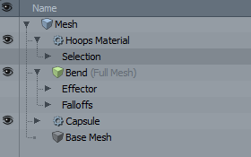
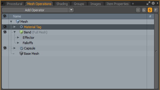
Procedural modeling lets you stack geometry and operations in the Mesh Operations List. Items are layered so that the items above affect the items below. This provides a simple structure for non-destructive modeling, as you can revisit a layer in the stack and change its settings. The image below shows a sample Mesh Operations list.
For more information, see Procedural Modeling.
Schematic Modeling
Modo has a Schematic viewport, which is a 2D environment where functional nodes are visually linked, providing a way to define, and redefine relationships between items and operations. You can build visual networks of items which can be combined to produce the desired result.
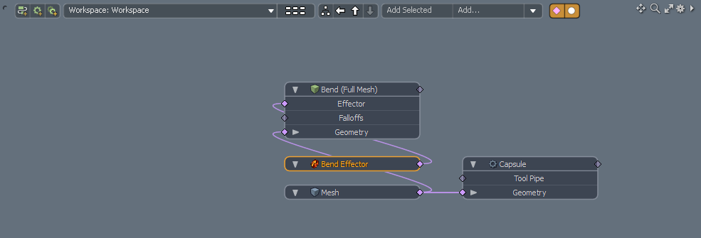
For more information, see Schematic Viewport.
MeshFusion Modeling
MeshFusion offers a sophisticated set of boolean operations for creating new geometry. With MeshFusion, you can create meshes through the non-destructive union, subtraction, and intersection of objects. Although similar in concept to existing Boolean operations, MeshFusion is significantly more advanced, supporting real-time update of operations and a high level of control over blending between the resulting surfaces.
Note: For more information, see MeshFusion.
Modeling Examples
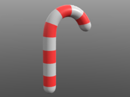
To give you a taste of how each of these approaches work, we are using a model of a simple striped cane.
Modeling the cane requires three main steps:
| 1. | Add a tall thin Capsule primitive. |
| 2. | Bend it using the Bend Effector. |
| 3. | Add the colored hoops by assigning a red material to rings of polygons. |
Capsule Settings
Learn how to perform these steps using each modeling technique.
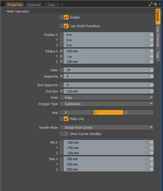
In each approach, a capsule primitive is added. Use the following settings to define the size and structure of the capsule:
• Position X, Y, and Z are 0
• Radius X: 100 mm
• Radius Y: 1 m
• Radius Z: 100 mm
• Sides: 24
• Segments: 9
• End Segments: 5
• End Size: 110 mm
• Axis: Y
Direct Modeling Example
Learn how to make the cane using the direct modeling workflow, starting with an empty workspace in Model layout.
Adding a Capsule
Add a capsule primitive to the scene and apply the Capsule Settings
| 1. | Click Layout > Layouts > Model. |
| 2. | On the left panel, click the Basic tab to view the modeling tools. |
| 3. | Click and hold on the Cylinder primitive button and select Capsule. |
Tip: Alternatively, right-click on the Cylinder primitive button and select Capsule.
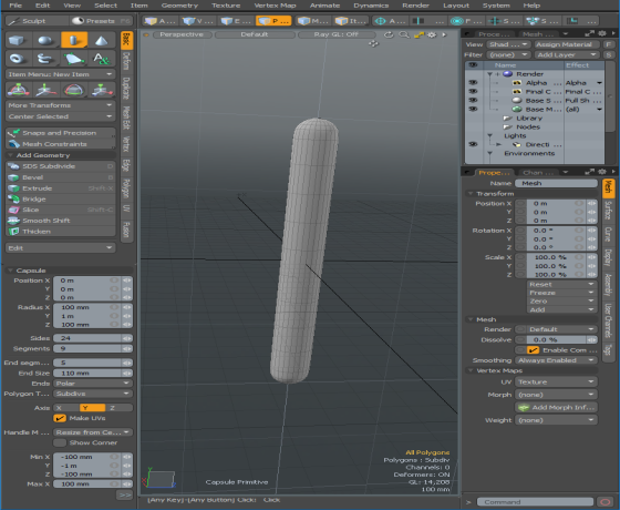
| 4. | In the Tool Properties panel, adjust the capsule settings as listed in the Capsule Settings and click Apply. |
Bending the Capsule
Bend the capsule using the Bend Effector tool.
| 1. | Click the Polygons selection mode tab and double-click on the capsule to select the entire item. |
Note: You must use either the Vertices selection mode or the Polygons selection mode when using the Bend tool to bend a specified area on the capsule.
Tip: Use Ctrl+Z to undo, if you are unhappy with the results.
| 2. | In the Toolbox, located on the left panel, open the Deform tab, and click Bend. |
| 3. | To initiate the interactive editing mode, in the 3D viewport, click at the base location of the capsule where the bend should start from. |
The Bend tool is activated.
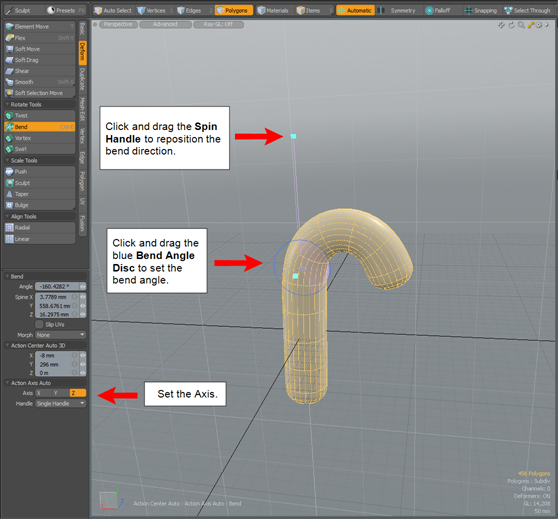
| 4. | In the Bend properties, listed in the left panel, set the Axis. In this example, it is set to the Z axis. |
| 5. | To set the bend angle, in the viewport, click and drag the blue Bend Angle Disc. |
| 6. | To reposition the bend direction, move the Spin Handle to the top of the cane item. |
Note: For more detailed information about the Bend tool, see Bend.
Adding Colored Hoops
Add colored hoops to the cane by assigning a red material to rings of polygons.
| 1. | In the Model layout, select the Polygons selection mode. |
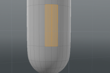
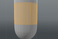
| 2. | To select a single hoop, select a polygon, and then press L to loop the selection. Repeat this step for every loop you want to color red. |
|
|
| 3. | Press M to assign a material to the hoops. In the Polygon Set Material dialog, name the material Hoops, click the Color value and select a red color. Click OK to close each dialog. |
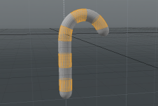
| 4. | Press the space bar to drop your selection. |
A colored candy cane, using direct modeling, is created. You can no longer change the properties of this model.
| 5. | Press F8 to preview the render output. |
Procedural Modeling Example
To model the cane procedurally, use procedural operations in the Mesh Operations list. All of the items added to the Mesh Operations list can later be modified.
Tip: Many of these steps involve adding procedural operations to the Mesh Operations list by navigating the directories in the Preset Browser. You can also locate an operation in the Preset Browser using the find functionality. To enable this, click the F button in the top right of the browser.
Adding a Capsule
Add a procedural capsule primitive to the Mesh Operations list and apply the Capsule Settings
| 1. | Click Layout > Layouts > Model. |
| 2. | On the top right panel, open the Mesh Operations list. |
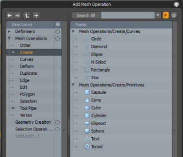
| 3. | From the Mesh Operations list, click Add Operator. |
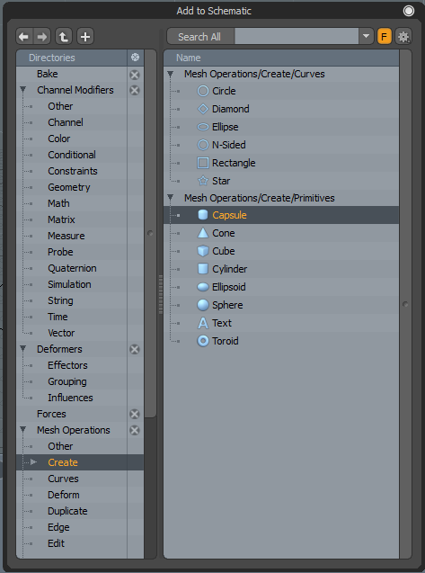
The Preset Browser is displayed.
| 4. | Click Mesh Operations > Create > Mesh Operations/Create/Primitives and double-click on Capsule. |
| 5. | In the Item Properties panel, adjust the settings as list in the Capsule Settings. |
Bending the Capsule
Bend the capsule using the Bend Effector tool.
| 1. | In the Mesh Operations list, click Add Item, select Deformers > Effectors, and double-click Bend Effector. |
| 2. | In the Item Properties, select the Bend Effector tab, and set Angle to 190°. |
Adding Colored Hoops
Add colored hoops to the cane by assigning a material tag to the Mesh Operations list.
| 1. | In the Mesh Operations list, click Add Operator, select Mesh Operations > Polygon, and double-click Material Tag. |
| 2. | In the Item Properties, select the Material Tag tab, and change Material Name to Hoops Material. |
| 3. | Activate the Polygons selection mode, select a polygon, and press L to complete the loop. Repeat this step for every loop you want to color red. |
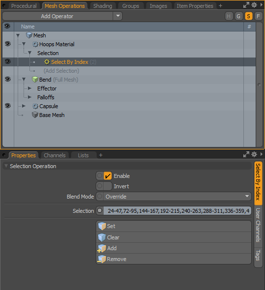
| 4. | To add the selection to the material, in the Mesh Operations list, expand Hoops Material, and expand Selection. Click (Add Selection) and double-click Select By Index. |
The selection is automatically populated with the polygons.
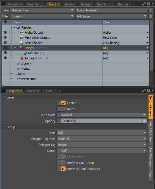
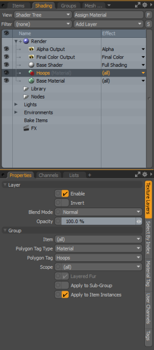
| 5. | To add a material group to the Shader Tree, click the Shading tab, and select Add Layer > Group. |
| 6. | In the Shader Tree, with the material group highlighted, select Add Layer > Material. |
Tip: If the Shader Tree tab is not displayed, click the plus sign to open a new tab and then select Data Lists > Shader Tree.
| 7. | Select the Material Ref properties and change the Diffuse Color to red. |
| 8. | To match the group to the Material Tag in the Shading properties, select the Texture Layers tab, ensure the Polygon Tag Type is set to Material, and set Polygon Tag to Hoops. |
A colored candy cane, using procedural modeling, is created. You can change the properties of this model at any point.
| 9. | Press F8 to preview the render output. |
Schematic Modeling Example
To model the cane schematically, use the schematic nodes in the Schematic viewport. Modeling schematically is normally performed in the Setup layout.
Adding a Capsule
Add a capsule node to the scene and apply the Capsule Settings
| 1. | Click Layout > Layouts > Setup. |
| 2. | In the Schematic viewport, click Add... to open the Preset Browser. |
| 3. | Select Mesh Operations > Create > Mesh Operations/Create/Primitives and double-click Capsule. |
| 4. | In the Item Properties panel, adjust the settings for the capsule as listed in the Capsule Settings. |
Bending the Capsule
Bend the capsule using the Bend Effector tool.
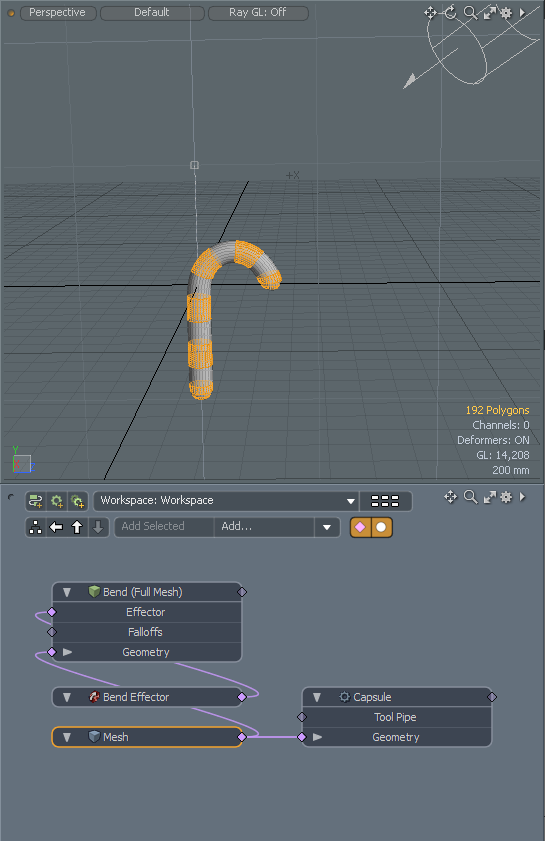
| 1. | In the Schematic viewport, click Add..., select Deformers > Effector, and double-click Bend Effector. |
A Bend Effector node is added and automatically wired to the capsule.
| 2. | To show the hidden connection, double-click the diamond connector on the Geometry input of the Bend node. |
| 3. | Click the Bend Effector node. |
The node is highlighted in yellow.
| 4. | In the Item Properties panel, select the Bend Effector tab, and set Angle to 190°. |
Adding Colored Hoops
Add colored hoops to the cane by assigning a material tag to the Mesh Operations list.
| 1. | In the Schematic viewport, change the View Type to Default to see the polygons clearly. |
| 2. | Activate Polygons selection mode, click on a polygon, and press L to complete the loop. Repeat this step for every loop you want to color red. |
| 3. | To add a Material Tag, click Add..., select Mesh Operations > Polygon, and double-click Material Tag. |
Notice that Select By Index is automatically added to restrict the material to the polygons that were selected.
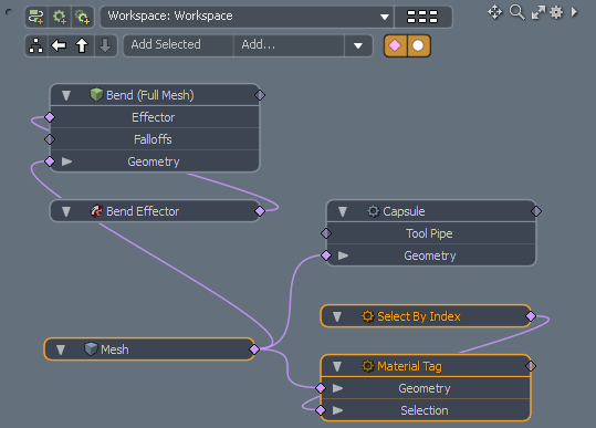
| 4. | To assign a name to the Material Tag, select the Material Tag node, and in the Item Properties panel, select the Material Tag tab. Set the Material Name to Hoops. |
| 5. | To add a material group to the Shader Tree, click the Shading tab, and select Add Layer>Group to hold the material. |
| 6. | To match the group to the material in the Schematic, select the Texture Layers properties, ensure the Polygon Tag Type is set to Material, and set Polygon Tag to Hoops. |
| 7. | To add the material to hold the color, in the Shader Tree, with the material group highlighted, select Add Layer>Material. |
| 8. | Select the Material Ref properties and change the Diffuse Color to red. |
| 9. | Press F8 to preview the render output. |
Adding to the Model
Now that you've tried all three approaches, test your knowledge further by coloring the non-red sections to something other than the red color. When using procedural and schematic modeling, you can also revisit the capsule and edit the settings such as the size or position. Try experimenting to see what happens. Also, try adjusting the Bend Effector settings.