Applying Snapping
Sometimes when positioning elements relative to each other, a high degree of precision is required, but zooming in to microscopic levels isn't accurate enough, nor is entering numeric values efficient (and neither is very user-friendly). In these cases, it is appropriate to use Snapping, a function that allows you to produce a highly accurate result, while maintaining a standard, interactive workflow.
Snapping in Modo is the action between two elements, one moving and the other static, where the moving element snaps to the static element's position, jumping away from the cursor when positioned within a user-defined range. This makes it easy to very accurately create and align elements in relation to one another, or in relation to 3D space.

Usage
Snapping is disabled by default, but it can be easily enabled by clicking the Snapping button over the interface window (highlighted above). Snapping is active when the button is highlighted in orange. You can also activate snapping with a shortcut by pressing X on the keyboard. To temporarily enable snapping during an operation, press and hold X to snap the element, and then release the key to disable. The X key is a toggle so it can also be used to disable Snapping. Hold it down during an action to temporarily disable Snapping for that action.
When snapping is enabled, it conforms to the settings of the Snapping Options panel where you can enable and disable specific scene features that trigger the Snapping action. The panel can be accessed one of two ways. In the Properties Panel, there is a persistent Snapping button. Click it to open the panel, or press F11 to open it under the mouse pointer. Click away from the panel to dismiss it. The various options of the Snapping panel are detailed further below.
To aid the snapping workflow, a number of pre-highlighting cues are employed for the cursor and target, when the cursor is close to the snapping range (the defined Outer Range control) the possible snapping targets highlight, making it easier to predict the possible snapping locations or as feedback that snapping has occurred.
Snapping Workflow
One of the most important things to keep in mind regarding snapping in Modo is that the Snapping function snaps a tool's handle, the widget that appears in the viewport when applying an action. The position and orientation of the active tool handle is controlled by the Action Center, so understanding these settings are important. Make sure to have an appropriate Action Center preset defined for the desired result.
By default, Modo has no defined Action Center (see Specifying Action Centers and Falloffs for more information). When you click in the viewport, Modo moves the active tool handle to the intersection point of the Work Plane and the mouse cursor's click. If you tried to click over a specific vertex, they might be exact (unlikely), they might be close, or they might not be close at all. Then, when moving the elements and snapping, the result would be very inaccurate and it would appear as if snapping failed. It actually didn't, It just wasn't told the correct thing to do.
To properly snap a single vertex to another single vertex, follow the steps below:
| 1. | First, enable the snapping feature option for Vertex and then set the Action Center to Selection Center Auto Axis. |
| 2. | Then select a single vertex, activate the Move tool (W) and moving the vertex, press and hold down X, to enable snapping temporarily. |
The single vertex then snaps to whatever new vertex the mouse hovers over.
| 3. | Release the mouse button and then press X to set the element at the snapped position. |
You don't need to set all these options each time using Snapping, as Modo remembers what setting was applied the last time it was used.
Tip: You can also define Snapping presets to easily apply within the Snapping Options panel, or by creating custom snapping controls specific to a single tool with the power of the Tool Pipe.
Snapping Options
To open the Snapping options, click Edit > Snapping > Snapping Options, or press F11 on the keyboard.
The Snapping Options menu allow you to control what scene features are snapped and when. You can select any number of controls simultaneously as well as the Mode that determines when the snapping occurs.
Snapping: This button enables and disables the Snapping functionality, same as the button above the modeling viewport.
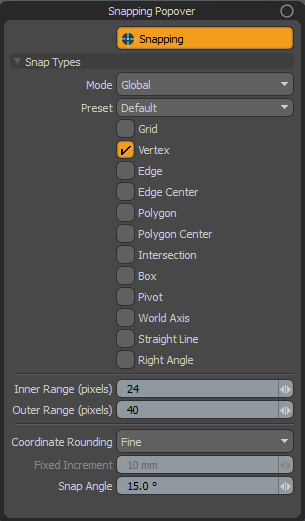
Snap Types
Mode: This defines different snapping features (listed below) depending on the current selection mode, with each Mode retaining its own individual definition. Click on the field to open the available options.
• Global: Determines the Snapping features that work globally, regardless of selection mode.
• Component: Determines additional Snapping functionality that applies concurrently to the Global values when working with vertices, edges and polygons.
• Items: Determines additional Snapping functionality that applies concurrently to the Global values when working with items, centers and pivots.
For example, you could set a Global mode snap option for Box and then a Component mode option for Vertex and Edge, and finally an Items mode option for Pivot. Then, when editing a vertex, which is a component, snap would adhere to the Global setting of Box, plus the component settings for Vertex and Edge, but ignore the Items settings of Pivot. Feel free to mix them up as you see fit.
Presets: Combinations of Snapping features can be stored as presets, making it easy to switch between often used combinations. To create a preset:
| 1. | Select the New Preset option from the panel. |
This opens a dialog box to enter a name for the preset.
| 2. | Type in a unique name for the preset and click OK to create the preset. |
The new preset automatically gets selected in the Preset list.
| 3. | While the named preset is selected, simply select any number of features in any Mode. |
They are saved into that preset automatically when the Snapping Options panel is closed.
To switch between different presets, select the named preset within the Preset list.
To remove a preset, select Remove Preset and then choose the named preset from the dialog and click OK.
Snapping Features: The following options all pertain to specific scene features that can be enabled/disabled. Multiple features can be selected at once and are stored independently for each Mode.
• Grid: When selected, you can define a fixed grid amount for snapping.
• Vertex: When selected, snaps to any individual vertex position.
• Edge: When selected, snaps to any position along a polygon's edge.
• Edge Center: When selected, snaps the center of the target edge.
• Polygon: When selected, snaps to any position of a polygon's surface.
• Polygon Center: When selected, snaps to the center of the target polygon. The center is the average position of all associated vertices.
• Intersection: When selected, snaps to the point of intersection between an edge and a polygon.
• Box: When selected, snaps to the cardinal positions of the target item's overall bounding box.
• Pivot: When selected, snaps to the pivot location of the target item.
• World Axis: When selected, tools align to XYZ axes. Only the Pen and Mirror tools support this snap type.
• Straight Line: When selected, snaps to a straight line. Only the Pen and any Pen generator type tools support this snap type.
• Right Angle: When selected, snaps to right (90°) angles. Only the Pen and any Pen generator type tools support this snap type.
Inner Range: Determines the range, in screen pixels, where a selected element snaps to the target element.
Outer Range: Determines the range, in screen pixels, where pre-highlighting occurs. When snap element and target element are within this proximity range, the target element highlights.
Coordinate Rounding: This option controls how mouse input is converted, through the Work Plane, into 3D coordinates.
• None: This means that no coordinate rounding is done. Every mouse move gives unclamped coordinates (typically with lots of decimals). This option is basically the raw 2D to 3D transform. Useful for working freehand.
• Normal: This option attempts to give clean, round coordinates based on your view transform. As the mouse moves, you can see values that are rounded in your current unit system display in the information tab. The step size gets smaller or larger as you zoom in or out. You may need to move the mouse cursor 2-3 pixels to see values update.
• Fine: This option is similar to Normal, but optimizes for closer to one step of coordinate rounding from one pixel of mouse movement. This gives you finer grained input, but can be difficult to hit exact values.
• Fixed: This option uses the Fixed Increment preference to put a lower limit on both coordinate rounding and the grid. If you set the fixed increment to 10 mm that means the grid never gets finer than 10 mm, and all input is rounded to the nearest 10 mm even at high zoom. When zoomed out, however, the grid shows larger values but the step size always remains a multiple of the fixed increment.
• Forced Fixed: This option is similar to Fixed, but forces the size of the grid and the input step to match the increment exactly no matter the zoom level.
Fixed Increment: When the Coordinate Rounding is set to either fixed options, this value determines the fixed coordinate rounding grid.
Special Snapping Options
When certain snapping features are selected, additional options appear in both the Snapping Options panel and the tool Properties panel for added convenience. These allow you to define specific controls related to the selected Snapping feature.
Grid Snap
Snapping of selected element is fixed to a user-defined grid. This setting can be helpful in keeping values to whole numbers (eliminating numbers with decimals) and can make the construction of geometry that conforms to a grid far easier and more precise to create such as a blueprint or floor plan.
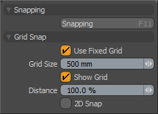
Use Fixed Grid: When this toggle is enabled, you can define a fixed grid with the Grid Size setting, which sets the snapping interval. When disabled, the grid snapping defaults to the dynamic grid displayed in the 3D Viewports.
Grid Size: When the Use Fixed Grid option is enabled, this value input filed defines the interval for the fixed grid, originating at the 0,0,0 World Origin position.
Show Grid: This toggle displays the grid as a light magenta overlay in the viewport, which dynamically updates similar to the Work Plane, in the center of the viewport as a visual reference to the Grid Size setting.
Distance: This option defines the snapping range, the distance when Modo snaps to the closest grid position. When set at the default 100%, Modo always keeps values fixed to the grid. Reducing this value would require the cursor to be closer to the grid positions before snapping occurs.
2D Snap: The 2D snap function relates to the orthographic viewports (top, front, side, and so on) that allow snapping on fixed planes parallel to the viewport window. This allows you to move points so they snap into position in the viewport, but they don't necessarily snap into a co-located position in 3D space.
Geometry Snap
Snapping to specific component elements. These snapping options allow you to very precisely position geometric elements in relation to one another.
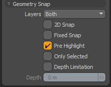
Layers: Instructs Modo as to which layers it should consider for snapping. Background only takes into account layers that are visible but not selected, Active only takes into account selected visible layers (also known as foreground layers) and Both which takes into account all visible geometry in the Items List.
2D Snap: The 2D snap function relates to the orthographic viewports (top, front, side etc.) and allow snapping on fixed planes parallel to the viewport window, thus allows you to move points so they snap into position in the viewport, but they don't necessarily snap into a co-located position in 3D space.
Fixed Snap: This toggle, when enabled, forces Modo to only position the moving element to snapping positions, normally moving elements would move, and then snap as they neared an element, but Fixed Snap jumps the elements between snappable positions.
Only Selected: When enabled, geometry snapping finds the element to be snapped to from the selected polygons of the Foreground. This makes geometry snapping fast for heavy meshes. For more information see Geometry Snapping - Only Selection Example.
Geometry Snapping - Only Selection Example
The following workflow example demonstrate how to apply the Only Selection option.
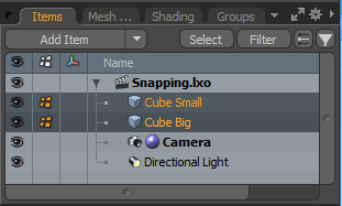
| 1. | Download our example scenes and open geometry_snapping-only_selection.lxo in the Model layout. |
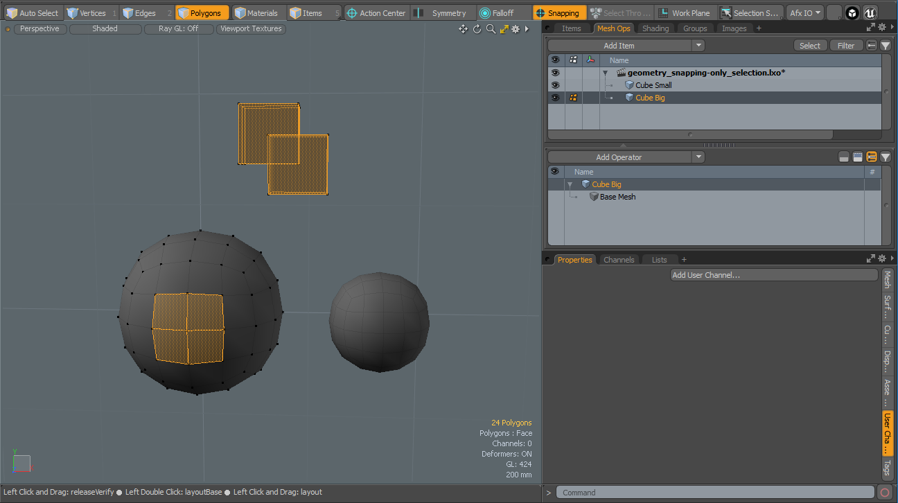
| 2. | On the right panel, in the Items list, select both mesh items; Cube Small and Cube Big. |
| 3. | On the application menu, click Polygons to enable this selection mode. |
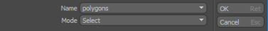
| 4. | From the Select > Use Selection Set menu, set Name to Polygons and Mode to Select, and then click OK. |
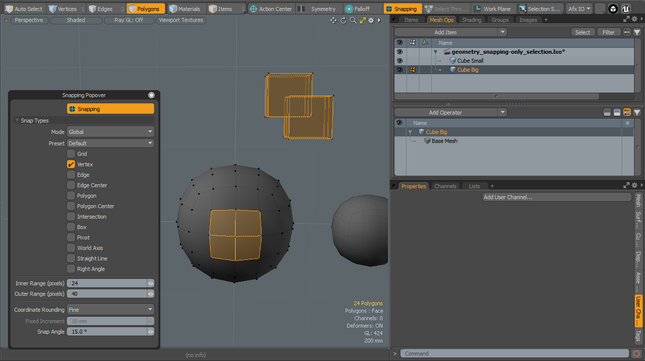
| 5. | From the application menu, click Snapping and press F11 to display the Snapping Popover dialog. |
| 6. | Enable the Vertex option. |
| 7. | On the Toolbox, located on the left panel, open the Curve sub-tab and click Curve to activate the tool. |
| 8. | Using the Curve tool, draw points over non-selected and selected polygons on both meshes. |
| 9. | With Curve tool still active, enable Only Selected in left side panel under the Geometry Snap options. |
| 10. | Continue using Curve tool to draw points over non-selected and selected polygons on both meshes. |
As you move the Curve handle, notice the Geometry Snapping Only Selected option locates the vector points and highlight them as you move over the polygon selection set of the Foreground.
Click the image below to view an animation.
Depth Limitation: When enabled, it limits the snapping range to the specified Depth. Snapping ignores elements further away from the source position. This is useful when working with complex scenes with lots of background objects, and you want to snap to specific things.
Depth: The maximum snap distance along screen direction used by the Depth Limitation option.
Pivot Snap Mode
Snaps selected element to items' pivot elements. This option can be helpful when several items need to pivot rotate from the same location.
Snap Size: This values defines how close an element must be to snap to the pivot position. Larger values snap elements more easily to the pivot position of an item layer.