Fit UVs
The Fit UVs tool scales the currently-selected UV data to fill the normalized 0 to 1 UV space. This is a very useful tool for optimizing UVs.
|
|
Activating the Fit UVs Tool
Direct Modeling:
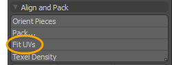
• With the UV layout open, on the left panel, expand Align and Pack, and do one of the following:
• click Fit UVs to apply the default properties. If these properties are changed, Modo preserves your settings and applies them the next time you use the tool.
• press Ctrl/Cmd + click Fit UVs... to open the properties dialog box and customize your settings.
• press Shift + click Fit UVs (Islands) to fit UV islands into 0-1 space of UDIM 1001 based on the size of the bounding box of each UV island (polygons overlap on top of each other).
• press Alt + click Fit UVs (Polygons) to fit UV islands into 0-1 space of UDIM 1001 based on the size of bounding box of every polygon individually (polygons overlap on top of each other).
• Alternatively, from the menu bar, click Texture > Open UV Editor, and click Fit to open the properties.

Procedural Modeling:
• In the Mesh Ops tab, click Add Operator, and double-click Mesh Operations > UV > UV Fit.
• In the Schematic view, click Add..., and double-click Mesh Operations > UV > UV Fit.
Direct Modeling Fit UVs Example
| 1. | With the UV layout open, on the right panel, select the mesh item in the Items tab you want to work with. |
| 2. | On the left panel, expand Align and Pack, and press Ctrl/Cmd + click Fit UVs... |
This opens the Fit UVs dialog. For more information, see Fit UVs / UV Fit Properties.
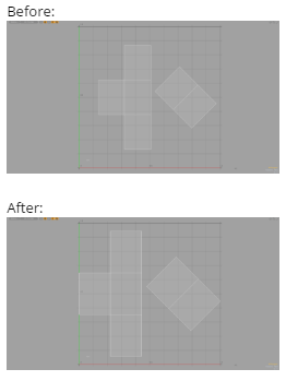
| 3. | Edit the properties and click OK. |
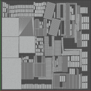
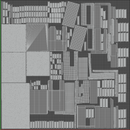
The following is an example of a cube using the default Fit UVs properties.
Procedural UV Fit Example
| 1. | Under the main menu, click UV to open the UV layout. |
| 2. | On the right panel, open the Mesh Ops tab, and select the mesh item you want to work with. |
| 3. | On the lower right panel, open the Lists tab, expand UV Maps, and select a UV map. |
The UV data is displayed in the UV viewport.
Tip: If you do not have a UV map created for your mesh item, on the left panel, click the dropdown arrow on Map: (none), and select New. 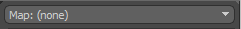 For more information, see Working with UV Maps.
| 4. | Click Add Operator and double-click Mesh Operations > UV > UV Fit. |
| 5. | Open the Properties tab on the right panel and edit the properties. |
For more information, see Fit UVs / UV Fit Properties.
Schematic UV Fit Example
| 1. | Under the main menu, click Setup to open the Setup layout. |
| 2. | On the top left corner of the interface, click UV View |
![]()
The UV viewport opens as a separate palette.
| 3. | On the right panel, open the Mesh Ops tab, and drag-and-drop the mesh item you want to work with onto the Schematic viewport. |
The selected node is added to the Schematic viewport.
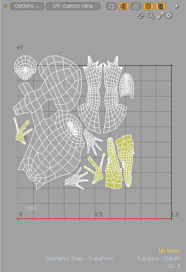
| 4. | If the UV map is not displayed in the UV View, click UV:(none), and select the UV map from the drop-down menu. |
![]()
| 5. | In the Setup Schematic viewport, click Add..., and double-click Mesh Operations > UV> UV Fit. |
| 6. | Open the Properties tab on the right panel, enter the name of your UV map, and edit the properties. |
For more information, see Fit UVs / UV Fit Properties.
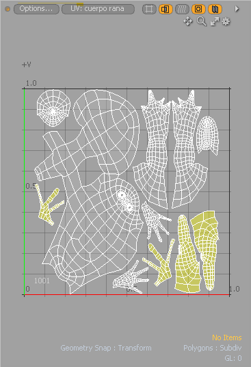
The UV data in the UV View palette is updated.
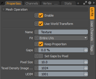
Fit UVs / UV Fit Properties
|
Enable |
Toggles the mesh operation off and on. This option is only available for a procedural modeling mesh operation. |
||||||||||||
|
Use World Transform |
When enabled, the mesh operation maintains the world space on the input layer. This option is only available for a procedural modeling mesh operation. |
||||||||||||
|
Name |
Specifies the output UV texture name. This option is only available for a procedural modeling mesh operation. |
||||||||||||
|
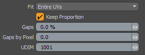
Fit |
Controls how the UV data is handled. The following options are available:
|
||||||||||||
|
Keep Proportion |
When active, the UV data scales proportionally so that the resulting UV data has the same ratio of height to width. The data scales until one of the maximum UV sizes is fit on one or both axes, but the data is not deformed to accomplish this. |
||||||||||||
|
Adds border padding to the UV map. By default the UV map is drawn up to the edge of the UV space, which may cause problems with pixel blending. Entering a percentage gap value corrects this type of problem.
|
|||||||||||||
|
Sets the padding to an image pixel unit. This option automatically updates the Gaps value. The Gaps by Pixel value is automatically calculated using the following equation: Gaps = Pixel Size / Texel Density Image Size. Tip: The pixel size is extracted from the Texel Density Image Size setting. To ensure that you have the correct image size, set the Texel Density Get Image Size option to use the background image. At the top of the UV Editor, click the Show Background Image icon to display the background image in the UV Editor. Setting the Gaps by Pixel value to the number of pixels you want to add as a gap places a border around the entire UV map. Gaps by Pixel is converted to Gaps when setting the pixel gaps in the command dialog. The Gaps by Pixel property is only available for the direct modeling Fit UVs tool. |
|||||||||||||
|
|
|||||||||||||
| Set Gaps by Pixel |
When enabled, Pixel Size is used instead of the Gaps attribute. This option is only available for a procedural modeling mesh operation. |
||||||||||||
|
Pixel Size |
The measurement of a single pixel in a UV unit. This value allows you use images scaled to real world size. This option defines the Gaps by Pixel based on the Texel Density Image Size.
This option is only available for a procedural modeling mesh operation. |
||||||||||||
|
Texel Density Image Size |
The size of the image that is used for the Texel Density to be mapped to. A Texel Density Image Size of 512 represents a Texel Density of 512 pixels per UV unit.
For more information on Texel Density, refer to the Texel Density documentation. Note: When using the direct modeling version of the Fit UVs command, the Texel Density Image Size can be adjusted from the Image Size option in the Texel Density panel on the UV Tab. This option is only available for a procedural modeling mesh operation. |
||||||||||||
|
UDIM |
Positions the UDIM indicator frame to the defined UDIM address location in the UV Editor. The UDIM property is only available for the direct modeling Fit UVs tool. |
||||||||||||