Vertex Tools
Create Vertex
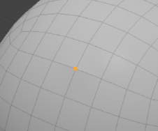
You can create vertices one at a time by specifying their location in 3D space. To do so, choose Geometry > Vertex > Create.
To create an individual vertex:
| 1. | Choose Geometry > Vertex > Create. |
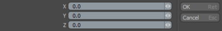
| 2. | In the Create New Vertex dialog, specify the X, Y, and Z coordinates for the vertex's location. |
| 3. | Click OK. |
The vertex is visible in the 3D model view.
Make Polygon
The Make Polygon tool uses the currently-selected vertices to create a polygon. The order in which the vertices were created (or selected) determines the direction of the polygons' normal. When run with an edge loop selection, a new polygon is created from those edges, and the selection order is not important. This command can be triggered by pressing the P key or by using Geometry > Polygon > Make, which offers several additional user-definable options.
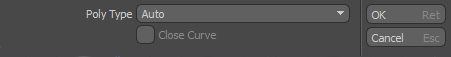
The following polygon types are available.
|
Faces |
Produces a regular polygon, based on the drawn vertices. |
|
Subdivs |
Generates a Subdivision Surface polygon, eliminating the need to toggle the newly-created geometry manually. |
|
Curves |
Generates a Spline curve from the points with the additional option to Close Curve, joining the in and out vertices into a loop. |
|
SplinePatch |
Produces a spline patch curve for further patching; this requires 3 or 4 vertices. |
|
Catmull-Clark |
Generates a Pixar Catmull-Clark Subdivision Surfaces polygon, eliminating the need to toggle the newly-created geometry manually. |
|
Polyline |
Generates a string of continuous polylines, similar to a curve but made from a string of line segments. These are often used as hair guides. |
|
Auto |
Matches the polygon type from a neighbor polygon connected to the selected vertex. If the selected vertices are floating, Modo chooses the Faces polygon type. |
Set Position
With the Set Position command you can reposition an existing vertex (or many) to a specific position by typing new coordinates. For example, you can center an entire loop of vertices on the zero position for a mirror operation.
| 1. | Select the vertices to change. |
| 2. | In the Toolbar on the left panel, go to the Vertex tab, and under Commands, click Set Position.... |
The command is also available in the menu bar, under Geometry > Vertex.
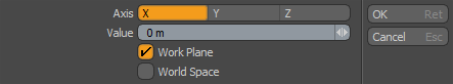
| 3. | Select the Axis along which you want to move your vertices, and specify the Value. |
To assign the position value based off the World Space or the Work Plane position, check the appropriate property.
| 4. | Click OK. |
The selected vertices are set to the new position.
Procedural Vertex Set Position
Set Position is also available as a mesh operation. It works the same way as its direct modeling equivalent.
Tip: For more information on procedural modeling and mesh operations, see Procedural Modeling.
| 1. | Select the vertices to modify. |
| 2. | In the Mesh Ops tab, click Add Operator. |
Tip: If the Mesh Ops tab is not visible on the right panel, click the + button on the right of the tab names, and select New Tab > Data Lists > Mesh Ops.
| 3. | Under Mesh Operations > Vertex, double-click Vertex Set Position. |
You can also find it in the Mesh Operations list.
| 4. | Select the Vertex Set Positon mesh operation in the Mesh Operations list. Its Properties appear in the lower-right panel. |
| 5. | Enable the axes you want to move the vertices along by checking Enable X, Y, or Z and set the Position for the relevant axes. |
The selected vertices are set to the new position.
Align
With the Align command you can align a selection of vertices into a straight row (in a line between the first and last vertices selected).
|
Option |
Description |
|
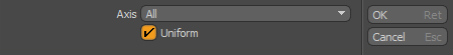
Axis |
Confines the movement of the repositioned vertices to one or All axes. You can also select an axial plane (XY, YZ, or ZX). |
|
Uniform |
When enabled, spaces the vertices evenly (uniformly) along the span. |
Join
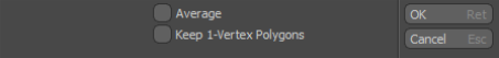
The Join command welds the selected vertices to the last vertex selected and then moves them all to the position of the last selected vertex.
You access the Join command on the Vertex tab of the Modo Tools toolbar.
|
Option |
Description |
|
Average |
When enabled, welds the selected vertices into a single vertex positioned at an average distance between the selected points. |
|
Keep 1-Vertex Polygons |
When enabled, allows single vertices to exist after the join operation. When disabled, Modo automatically deletes 1-vertex polygons. |
Join Averaged
The Join Average command welds two (or more) vertices together at a central position between the two vertices.
To join multiple vertices:
| 1. | Select the vertices to join together. |
| 2. | On the Modo Tools toolbar, click the Vertex tab. |
| 3. | In the Commands section, click Join Averaged. |
| 4. | In the Join Vertices dialog, read the message indicating how many vertices were joined into one. |
| 5. | Click OK. |
Remove
The Geometry Remove command deletes the selected vertices, edges, or polygons from the 3D model view.
You can use the Remove command from the Vertex or Edges tab of the Modo Tools toolbar or choose Geometry > Remove. Also, you can use the Backspace or Delete key to remove vertices, edges, or polygons. Geometry Remove works on individual or multiple selected vertices, edges, or vertices.
Collapse
The Collapse command removes the selected element without destroying the integrity of the geometry. You can delete any selected polygon, edge, or vertex but, with this command, no hole is left behind. Instead, Modo heals the mesh to close any gaps by merging neighboring elements together.
You access the Collapse command in several places:
• Vertex: On the Vertex tab of the Modo Tools toolbar click Commands > Collapse.
• Edge: On the Edge tab of the Modo Tools toolbar click Commands > Collapse Edges.
• Polygons: On the Polygons tab of the Modo Tools toolbar click Commands > Reduce > Collapse.
• You can also select whatever geometry to collapse and then choose Geometry > Collapse.
Split
The Split command for vertices is the opposite of the Join command. Instead of combining multiple vertices into a single vertex, this command takes a single vertex and creates multiple vertices in the same location based on the number of polygons that share the point.
To use the tool:
| 1. | Select the vertices to split. |
| 2. | In the Toolbar on the left panel, go to the Vertex tab, and under Commands, click Split. |
The command is also available in the menu bar, under Geometry > Vertex.
Unlike the Join command, Split creates the multiple vertices in their original location, it doesn't move them apart. Select any polygon or edge and move it to separate the split vertices.
|
|
|
|
The vertices after applying Split. |
Moving an edge reveals that the vertices are split. |
Procedural Vertex Split
Vertex Split is also available as a mesh operation. It works the same as its direct modeling equivalent.
Tip: For more information on procedural modeling and mesh operations, see Procedural Modeling.
| 1. | Select a vertex to split. |
| 2. | In the Mesh Ops tab, click Add Operator. |
Tip: If the Mesh Ops tab is not visible on the right panel, click the + button on the right of the tab names, and select Data Lists > Mesh Ops.
| 3. | Under Mesh Operations > Vertex, double-click Vertex Split. |
The mesh operation is applied to your geometry and you can also find it in the Mesh Operations list. If you then move a connected edge or polygon, the split vertices are revealed. The following example shows the Edge Slide mesh operation applied to a connected edge.
Merge
The Merge Vertices command measures the distance between vertices in the currently selected geometry to see if any fall within a specific distance threshold to one another. If any vertices are within that range, Modo combines them into a single vertex. It positions the resulting vertex at the site of the most recently selected vertex of the merged vertices.
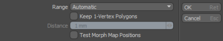
The Merge command is on the Vertex tab of the Modo Tools toolbar in the Tools section. The following options are available:
|
Option |
Description |
|
Range |
Specifies when to merge vertices. By default, the Merge Vertices command uses a Range setting of Automatic. • Automatic: Merges only vertices that share the exact location on all three axes. • Fixed: Provides a way to specify a distance threshold. Select to increase the distance allowed between two vertices to be merged. After selecting Fixed, you can set a threshold value for the Distance. |
|
Keep 1-Vertex Polygons |
When enabled, leaves behind any 1-vertex polygons from merging vertices. Often when merging vertices within a certain threshold, polygons become flattened into only one vertex. In this case they become 1-vertex polygons. These 1-vertex polygons can cause rendering anomalies and other issues in the model file when exporting to other systems. When disabled (by default), Modo removes these 1-vertex polygons. However, there are some cases where you may want to keep the resulting 1-vertex polygons. |
|
Distance |
Specifies the distance threshold if you selected Fixed as the Range. For example, if the Distance is set to one meter, Modo merges any points that fall within one meter of another point. |
|
Merge Discontinuous UV Values |
Enabled by default, merges discontinuous UV values together into continuous data to optimize the UV map. |
Vertex Index Order
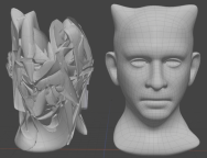
In order for mesh deformation to work correctly with morph influences, Modo assigns each vertex on a mesh a numerical index which becomes part of the vertex index order. This ensures each vertex on the mesh is mapped and stored correctly with the morph influence.
Note: See Morph Influence for more information on creating deformations with Morph Influences.
However, using mesh edit tools on the original mesh can change the index order, causing deformation issues between the edited mesh and the target mesh.
|
|
|
|
An example of a morph map with mismatched vertex index order. |
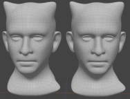
A fixed vertex index order between two meshes results in a correct morph. |
Reordering Vertex Index Order
There are two options in the Vertex tab to reorder the vertex order on your meshes:
- Reorder Index - assigns the selected vertices a new index order based on the Mode you choose. This allows you to repair specific vertices on meshes for deformation purposes, or repair game assets that require a strict index order.
- Sync Vertex Order - matches the vertex index order of one mesh to another mesh based on the polygons you have selected. You can use this option to fix mismatches in vertex index order between two meshes when you are creating a morph map between the two meshes.
Tip: Enable Show Indices in the 3D Viewport Properties to see the index number of a selected vertex in the viewport.
To fix the index order of specific vertices on a single mesh:
| 1. | Click Vertices on the Modo layout to enter Vertex Selection mode. |
| 2. | Select the vertices on the mesh in the order you would like them to appear in the index. |
| 3. | Click Reorder Index in the Vertex tools tab. |
| 4. | Select a Mode from the dropdown: |
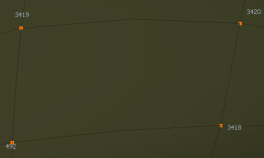
- Swap - Assigns the selected vertices a new index order based on the original indices of the selected vertices, and the order in which the vertices are selected. In the following image on the left, the vertices were selected in the following order: 3420, 3418, 492, 3419. After Swap mode was assigned in the image on the right, the selected vertex order became 492, 3418, 3419, 3420.
|
|
|
|
The original index order of the selected vertices. |
The new index order of the selected vertices when selecting Bottom mode. |
- Top - The selected vertices are moved to the top of the index order based on the order the vertices were selected. The first vertex to be selected is assigned an index of 0. All unselected vertices are appended to the new index. In the following image on the left, the vertices were selected in the following order: 3420, 3418, 492, 3419.
|
|
|
|
The original index order of the selected vertices. |
The new index order of the selected vertices when selecting Bottom mode. |
- Bottom - The selected vertices are moved to the bottom of the index order based on the order the vertices were selected. The last vertex to be selected is assigned the final index number in the list on the entire mesh. All unselected vertices on the mesh are appended before the new index. In the following image on the left, the vertices were selected in the following order: 3420, 3418, 492, 3419.
|
|
|
|
The original index order of the selected vertices. |
The new index order of the selected vertices when selecting Bottom mode. |
| 5. | Click OK. |
To fix a mismatch in vertex index order between two meshes with the same topology:
- Click Polygons on the Modo layout to enter Polygon Selection mode.
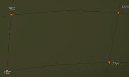
- Hold Shift and select two polygons on one mesh, then hold Shift and select the same polygons on the second mesh.
- Click Sync Vertex Order in the Vertex tools tab.
Four polygons are selected.
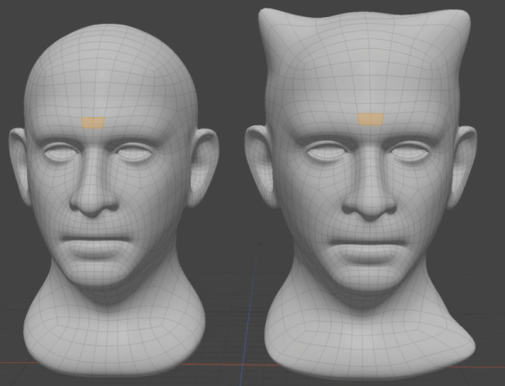
The same two polygons on the source and target mesh are selected.
The vertex index order on the two models are synchronized, and a dialog appears displaying the amount of vertices that were reordered. In this example, the mesh heads had 81 vertices out of sync with one another.
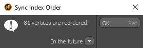
The Sync Index Order dialog.
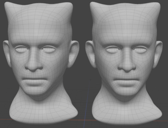
The source mesh correctly using the target mesh as a morph influence.