UV Viewport
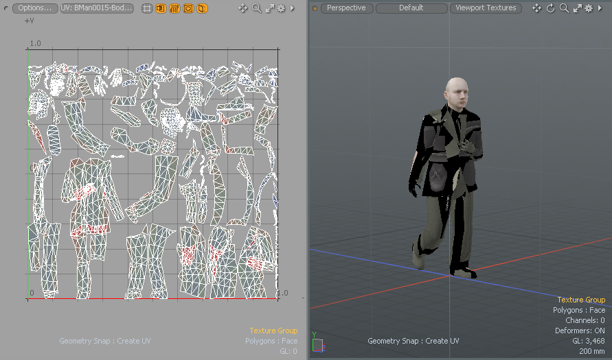
The UV viewport is much like the 3D (OpenGL) Viewport. It displays the 3D space as well as a two dimensional view of UV space. UV maps are the flat, 2D representations of a model's 3D surface for the application of texture maps (images). For more information about texture maps, see Working with UV Maps.
To open the UV Viewport:
• From the menu bar, click Layout > Layouts > UV.
• In the switcher bar, disable the Starred Only button and click UV.
• To work in a standalone UV Editor, click Texture > Open UV Editor.
For more information, see Working in the UV Editor.
Working in the UV Viewport
The UV viewport displays the UV space in a 2D UV grid with a flat background color. You can customize the UV viewport by using the buttons and controls.
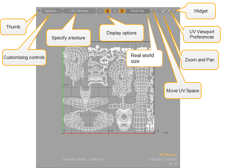
Thumb and Widget Controls
![]()
To detach, clone, split, or scale the viewport:
• Click and drag the Thumb control to detach.
• Right-click to select a viewport option.
Tip: If the UV Viewport is not visible, double-click on the UV layout tab to restore the default settings.
To change the viewport preset:
• Click the Widget control and select another viewport style.
For more information, see Using Layout Controls.
Move, Magnify, and Scale Controls
![]()
• Click and drag to move, magnify, and scale the contents in the viewport, making it easier to see certain areas for detailed editing.
Available shortcuts:
• Ctrl/Cmd +Alt+click - zoom to mouse position.
• Alt+click - pan view.
Mouse wheel - zoom to mouse position.
• Shift+Alt+middle-click - pan horizontally (U direction).
• Shift+Alt+right-click - pan vertically (V direction).
• Ctrl/Cmd +Alt+right-click - box zoom (drag to define zoom area).
• A - fits and centers geometry to the viewport size.
• Shift+A - zoom to selection.
• . (period) or , (comma) - zoom in and out.
• G - center current mouse position.
Customize Viewport Controls

• Click Options to change the Customizing the UV Viewport.
Replace or Create a Texture
• Click UV: (none) to replace or use a new UV texture on the mesh surface. The text in the button displays the name of the UV texture selected.
For information about how to create a UV Texture map, see Create UV Tool.
Note: When applying UV Textures to a Preset mesh, the UV Map name for the UV Texture must be the same as the UV Map name used by the Preset. For more information about presets, see Preset Browser. For more information about renaming UV Maps, see Working with UV Maps.
Change Display Options
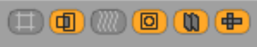
Click a display icon to update the UV viewport.
• Auto Spans - draws the UV space with grids regardless to the size of the patches.
• Show Overlap - displays a red highlight to indicate the overlapping UV state.
• Show Distortion - display the distortion colors. For more information, see Displaying Distorted UVs.
• Show Image - displays a background reference image map. For more information, see Modeling with Images.
• Show Inactive UVs - toggles the visibility of UVs for items not selected in the Items list.
• Show Wireframe - toggles the visibility of wireframes.
For more detailed information, see Customizing the UV Viewport.
Adding Real World Size to UV Maps
Real world materials are often scanned and imported into 3D applications in real world sizes to ensure they are applied at the correct scale to the 3D model. For example, you could have a scanned square of material that is 10cm wide and high which you want to appear at the correct scale when applied to your models.
In Modo, you can define the real world size of your UV maps to ensure scanned materials and AxF materials are applied to your meshes at the right scale.
To define the real world size of a UV map:
- Click the UV layout so you can see the UV viewport.
- Select the UV map where you want to assign a real world size.
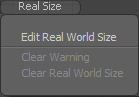
- Click the Real Size button at the top of the UV viewport, and select Edit Real World Size.
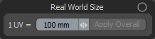
- Enter a value in millimeters for the real world size of each UV tile.
- Click Apply Overall.
Note: See Replace or Create a Texture to learn how to create or select UV maps.
For example, if you want each UV tile in the UV map to be 10cm, enter a value of 100mm.
Note: If the Apply Overall button is disabled, it means you have not selected a UV map.
The size is assigned to the UV map, and the size of the selected UV map appears at the top of the UV viewport.

To clear existing real world sizes on selected UV maps, click the Real Size button and select Clear Real World Size.
Note: See AxF Material and Texture Locator for more information about using the real world size on textures and materials in Modo.
Working in the UV Editor
Use the UV Editor as a standalone viewport while working in another layout, such as Model. Common tools are available in this viewport. To open the UV Editor, click Texture > Open UV Editor.
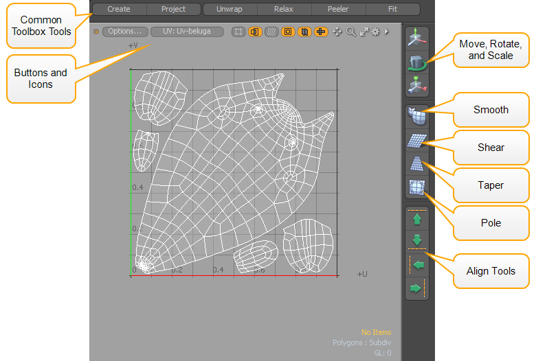
For information about the common tools located on the right of the UV Editor, see Move, Shear, Smooth, Taper, and Align UV
Toggling Visibility
Generally, you can toggle visibility of items in the Items (Scenes) List, which changes visibility of the entire layer. Commands are also available to temporally toggle the visibility for selected items. Once hidden, geometry is uneditable, meaning it cannot be selected or moved.
• In the 3D viewport, select the geometry component you wish to hide and click View > Hide Selected or press H.
• To make the geometry visible again, click View > Unhide command or press U.
When a file is saved and re-opened later, all hidden polygons are visible.
Tip: By dragging over an object, you can paint a selection of one of more items. If you right-click and drag, you can draw a lasso around the selection area to select multiple items at once.
Visibility Shortcuts
• H - hide selected (hides all if nothing is selected).
• Shift+H - hide unselected
(hides all unselected geometry).
• Ctrl/Cmd +H - hide invert (toggles visibility, inverting the present state).
• U - unhide (makes all hidden geometry visible).
Locking Geometry
Locking provides a similar function to hiding, allowing you to fix a selection of geometry so that it is immovable and un-selectable, effectively un-editable. However, it is still fully visible. Unlike hiding, this locking function is limited to the component selection modes.
• Select geometry and click Edit > Lock Selected or press J.
• You can unlock any locked element in an item layer with Edit > Unlock or by pressing I.
Locking Shortcuts
• J - lock selected (locks all if nothing is selected).
• Shift+J - lock unselected (lock all of the unselected geometry).
• Ctrl+J - lock invert (toggles locked state of all geometry).
• I - unlock (makes all locked geometry editable).
Displaying Flipped UVs
You can display the orientation of your UV shells within the UV viewport. Flipping a UV shell is useful if you need to correct a texture that is reversed.
From the Options button, enable the Show Flipped option in the context menu to display flipped UVs in yellow. You can also display flipped UVs with overlapped UVs. If both are present, the color is blended.
Tip: The Show Flipped option is also available in the UV Editor (Texture > Open UV Editor).
Flipped UVs may occur when you Mirror selected geometry. The following example displays flipped UVs and how to correct their orientation. For more information about how to use the Flip UV tool, see Flip UV.
Click the image below to view an animation.
Watch this video for an overview.
Reviewing UV Coverage
When you create a UV map, the UV coverage indicator displays a percentage value in the lower right corner of the UV viewport and UV Editor, representing the amount of uniform UV space of the total region that is covered by geometry. This information is useful when trying to maximize the amount of texture space being used by the target surface.
If you select only a few geometry items in your scene, the UV coverage indicator displays a percentage value representing the coverage used for the selected items and a percentage value representing the coverage used by the remaining items on your UV map. For example, when viewing the background and foreground items in a UV map, the active selected geometry is displayed in white, while the inactive geometry is displayed in black. Clicking on either item displays the coverage usage for that selection.
Selecting Items
You can select individual UV maps in the UV viewport and in the UV Editor using paint selection and lasso selection while in Items Selection Mode selection mode.
Tip: By dragging over an object, you can paint a selection of one of more items. If you right-click and drag, you can draw a lasso around the selection area to select multiple items at once.
If you have individual UV maps using the same name for each mesh item in your scene, the active UV map displays in white in the UV viewport and the non-active (not selected) UV maps display in black.
• You can use the draw selection or lasso selection to activate individual UV maps.
• You can also make your selection in the 3D viewport by clicking the UV wireframe.
Displaying Distorted UVs
Two main goals when working with UV maps are to eliminate or reduce seams, and to minimize distortion from stretching. Unfortunately, these two are not mutually exclusive. Distortion often happens with UV mapping.
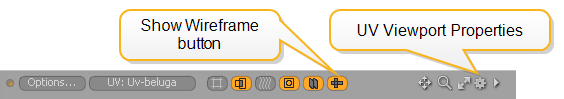
To enable distortion visibility, click the Show Distortion ![]() button or open the UV Viewport Properties, and enable Visibility > Show Distortion.
button or open the UV Viewport Properties, and enable Visibility > Show Distortion.
Enabling the UV Viewport option displays a color overlay on the geometry, fading toward red when polygons are distorted and smaller (relative to other polygons in the map) and fading toward blue when they are distorted and larger, relative to other polygons. Polygons that are the closest relative size to others in the map with the least distortion display a middle gray/green color. You can also display the distortion colors in the 3D viewport by clicking the Show Distortion ![]() button at the top of the viewport.
button at the top of the viewport.
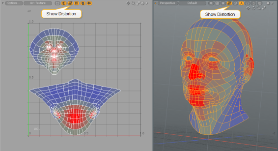
When you're working with dense meshes, it might be difficult to see the distortion map. In such cases, you can disable the wireframe visibility by clicking the Show Wireframe ![]() button at the top of the viewport, or disabling Show Wireframe in UV Viewport Properties > Visibility. For more information on properties, see Customizing the UV Viewport.
button at the top of the viewport, or disabling Show Wireframe in UV Viewport Properties > Visibility. For more information on properties, see Customizing the UV Viewport.
Customizing the UV Viewport
You can select from a variety of display customization options from the UV viewport Properties menu.
To open the properties:
• Click the gear ![]() icon in the upper-right corner.
icon in the upper-right corner.
• Hold the mouse pointer over the viewport and press O.
• Click to set common viewport options.
Drawing and Control Options
Click the Gear icon on the top of the UV viewport to open the UV Viewport Properties.

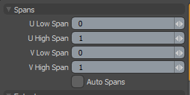
Spans
|
U/V High/Low Spans |
Controls the number of UV sections or spans displayed in the viewport. Each span represents a complete UV grid section. The default value produce the grid found most commonly in 3D programs representing, the -1 to 1 UV space coordinates. You can place vertex data anywhere within UV space; this option simply determines the display extent of the UV grid. |
|
The Auto Spans option fills the UV space with grids. |
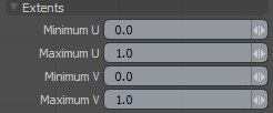
Extents
|
Minimum/Maximum U/V |
If you have Show Image enabled with an image selected, you can control the UV area where your image map is displayed. |
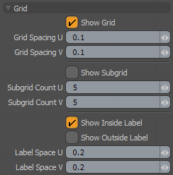
Grid
|
Show Grid |
Toggles the visibility of the UV grid in the viewport. |
|
Grid Spacing U/V |
Sets the grid line spacing using these values, defined as decimals of the UV unit. The default value of 0.1 draws grid lines every 10th of a unit. |
|
Show Subgrid |
Displays a lighter secondary grid. Use this option for detailed maps, as the standard grid may not have enough sub-divisions to be visible when zoomed in. |
|
Subgrid Count U/V |
Determines the number of divisions between each Grid sub-division. |
|
Show Inside Label |
Toggle the grid value labels inside the grid area. |
|
Show Outside Label |
Toggle the grid value labels outside the grid area. |
|
Label Space U/V |
Determines the division level for the grid labels. Typically this value matches or is a division of the Grid Spacing value. |
|
Grid Spacing U/V |
Sets the grid line spacing using these values, defined as decimals of the UV unit. The default value of 0.1 draws grid lines every 10th of a unit. |
|
Show Subgrid |
Displays a lighter secondary grid. Use this option for detailed maps, as the standard grid may not have enough sub-divisions to be visible when zoomed in. |
|
Subgrid Count U/V |
Determines the number of divisions between each Grid sub-division. |
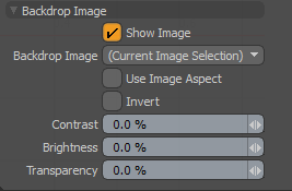
Backdrop Image
|
Toggles the visibility of a background reference image map. The image displayed is determined by the Backdrop Image settings. |
|
|
Backdrop Image |
Select from a list of loaded images (those that are available in the Clips/Image list). ] When the option is set as Current Image Selection, the current image selected is used as the backdrop. Images can be selected in the Images tab or within the Shader Tree. |
|
When enabled, the UV window is scaled horizontally to match the aspect ratio of the selected image, making it easier for you to edit UV maps for non-square aspect ratios. |
|
|
Invert |
Inverts the RGB color values of the backdrop image, producing a negative effect. |
|
Contrast |
Sets the visual difference between light and dark values in an image. Values greater than 0% increase the contrast of the backdrop image, while values lower than 0% decrease it. |
|
Brightness |
Sets the degree or amount of light or luminosity in an image. Values greater than 0% increase the brightness of the backdrop image, while values lower than 0% decrease it. |
|
Transparency |
Determines the opacity of the backdrop image. Values greater than 0% increase the transparency, ramping toward 100%, where the image becomes completely transparent. |
Visibility Options
Click the Gear icon on the top of the UV viewport to open the UV Viewport Properties.
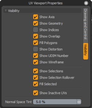
|
Show Axis |
Toggle the colored axes displayed in the viewport. |
|
Show Geometry |
Toggle the displayof all geometry in the viewport. |
|
Show Indices |
Toggle the display of vertex index values for selected items. |
|
When the area of a polygon sits over the area of another, enabling this option displays a red highlight to indicate the overlapping state. |
|
|
Fill Polygons |
Toggle the visibility of the faint fill coloring given to polygon faces. |
|
Toggle the display of the distorted UVs. When enabled, colors overlay onto the geometry signifying distorted areas of the UV map. For more information, see Displaying Distorted UVs. |
|
|
Show UDIM Number |
Toggle the displays the UDIM address at the center of each UDIM tile. The UDIM number is displayed in the bottom left corner of the UV space. |
| Show Wireframe | Toggle wireframe display. When working with dense meshes with UV distortion enabled it can be difficult to see the distortion map. This option is useful to make dense UV maps easier to see. |
|
Show Selections |
Toggle the display of highlighted polygon selections (by default, an orange color). |
|
Show Selection Rollovers |
Toggle the display of selection rollover. |
|
Fill Selected |
Toggle visibility of the orange fill color for selected polygons. |
|
Toggle the display of UV maps for items in the background (visible but not selected in the Items list). |
|
|
Normal Space Tint |
Controls the amount of tint coloration applied to the areas in UV space that don't contain UV patches, identifying the central or main UV area of 0 to 1. This is where textures originate; outside of this area the texture simply tiles. |