Bend
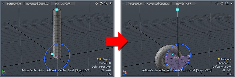
With the Bend tool you can quickly deform selected geometry in a curved manner. For example, take a straight cylinder (or a tube) and flex it into an arc to produce a section of a torus. This is similar to what the Bend tool does. The Bend tool consists of two handles: a bend spine and the bend angle disc. These control what gets bent and how much Modo deforms the geometry respectively.
Usage
To use the Bend tool, click the tool's button in the Deform sub-tab of the default modeling toolbox. This activates the tool and shows the tool's attributes in the tool's Properties panel. Next, in the 3D viewport, click at the base location (where the bend should start from) to initiate the interactive editing mode and then draw the tool's handles. The center of influence for the Bend tool is at the intersection of where you click initially and the Work Plane. You may need to position the Work Plane appropriately prior to activating the tool because the Work Plane also determines the initial orientation of the tool.
Modo provides two handles to bend the target. The circular Angle handle, which is similar to the standard Rotate tool's handle, controls the amount of bending. The Spine handle determines the influence area for the operation. You can drag the Angle handle in a circular direction. The greater the distance is from where you clicked initially, the greater the bend amount is. Also, if you move the pointer (while dragging) further away from the handle, you have finer control for determining the angle. The spine determines which area of the target Modo bends. When you click and create the tool handle, its height is determined by the bounding box height of the target geometry. Because of this, Modo can deform the entire length of the target. You can drag the small blue square at the top of the handle to change its length to have a partial bend deformation. If you move the pointer over the blue square, Modo changes its color to yellow and dragging moves it. Dragging adjusts the position of the spine on the axes relative to the Work Plane. Pressing Ctrl while dragging constrains the move to a single axis. You can adjust the options in the Properties panel manually while the tool is active for a more precise bending deformation.
|
Bend |
|||||
|---|---|---|---|---|---|
|
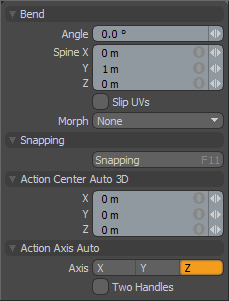
Angle |
Represents the amount of bend that is received by the geometry at the end of the spine. The Bend tool automatically fades this amount across the geometry selection down towards the base of the Bend tool to accomplish the intended bending effect. |
||||
|
Spine X/Y/Z |
Sets the end of the spine handle. You can adjust the handle interactively in the 3D viewport by dragging or by typing positional values in the boxes. |
||||
|
Slip UVs |
When enabled, edits applied to the geometry do not change the existing UV map. UV values are generally fixed to specific vertices; therefore, further edits to the geometry may warp, deform, or otherwise distort the UV values in undesirable ways. When this happens, you may need to adjust the map or to redo it altogether. To avoid this undesirable result, you enable Slip UVs so as to not disturb any existing UV mapping applied to the geometry.
|
||||
|
Morph |
Determines how Modo treats stored morphing information when applying transforms (such as the Move, Rotate, or Scale transforms) to geometry. There are three options for controlling how Modo deals with the morph map vertex data when applying any transforms. • None - Transforms selected (visible) morphs independent of their source, but does not affect unselected morph data.
• Transform - Transforms morph data along with the base mesh.
• Keep Positions - Converts morph data into an absolute morph map. All vertices retain their pre-transformed positions. Note: In previous versions of Modo, to transform a morph along with its base, you needed to select it in the Vertex Map list. If you didn't, when Modo recalled the relative morph map data, it would produce distorted, undesirable results; therefore, it was easy to accidentally spoil a model. To remedy this problem, current versions of Modo have three options to deal with the morph map vertex data. |
||||
|
Snapping |
See the Applying Snapping topic for details about this feature. |
||||
|
Action Center Auto 3D |
Positions the Angle adjustment handle relative to the position of the Work Plane when you first activate the tool in the 3D viewport. For more information see the Specifying Action Centers and Falloffs topic. |
||||
|
Action Axis Auto |
Specifies an alternate axis if the initial selection is incorrect for the desired bending direction. |
||||
|
Two Handles |
When enabled, draws an additonal two handles in the 3D viewport for you to interactively adjust the orientation of the handle itself for off-axis bending. |
||||