Element Push
With the Element Push tool you can push individual component elements of a mesh (vertices, edges, or polygons) along their normals.
Using Element Push
You can find the tool in the Model layout's Deform sub-tab, or in the menu bar, under Edit > Deform > Element Push Tool.
| 1. | Activate the tool by clicking the Element Push button. |
As you move the pointer in the 3D viewport, selectable elements are highlighted
| 2. | Click and drag on a vertex, edge, or polygon to push it. Alternatively, click on an element to display the handles, and use those to push it along an axis. |
By default, the tool is in Auto mode, and Modo determines the element type to be edited when you click. For example, if you click an edge, you edit the edge; if you click a polygon, you edit the polygon. With this tool in Auto mode, you can edit components of the mesh independently of the current selection state. You can change the mode in the tool's Properties panel.
The Element Push tool also has an Element Falloff value, which creates a spherical area of influence around the element under the pointer. You can set this value in the tool's Properties panel, or by right-clicking and dragging in the 3D viewport. Modo represents this falloff in the 3D view by a yellow wireframe sphere for you to interactively adjust the region.
Element Push Properties
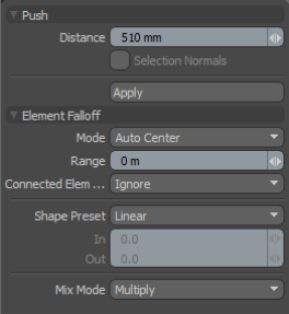
The following properties are available for the Element Push tool:
|
Push |
|
|---|---|
|
Distance |
The offset distance of the push. |
|
Selection Normals |
When enabled, Modo uses the normals computed from selections. Note: This option is only available in Polygons selection mode. |
|
Element Falloff |
|
|
Mode |
Defines the automatic center that the push offsets from when applied, as well as the element type selected under the pointer. Auto is the default for the tool to select whatever element the pointer is over. It positions the center where the pointer intersects the surface it is modifying. Other options give you finer control. |
|
Range |
Specifies a soft falloff region that attenuates the transform over the range's distance. |
|
Connected Elements |
Defines what connected geometry does when you push an element. • Ignore - Ignores all connected elements and only pushes the specified element. • Use Connectivity - Affects only single-surface or connected elements. Ignores unconnected elements within range. • Rigid Connections - Pushes all connected elements equally the specified distance. • Edge Loops - Pushes connected loops (all the connected polygons, edges, and vertices in a single row). |
|
Shape Preset |
Controls the strength of the falloff's influence along the extent by using a shape preset. • Linear - Attenuates the falloff evenly across its range. • Ease-In - Strengthens the falloff toward the start position. • Ease-Out - Strengthens the falloff toward the end position. • Smooth - Strengthens the falloff toward the center of the falloff. • Custom - Fine-tunes the strength of the falloff based on the In and Out values. |
|
Mix Mode |
Defines how each falloff interacts with the other(s), when there are multiple falloffs applied to a transform (by using Add in the Falloff menu). |