Applying Precision
Learn about symmetry, snapping, constraints, and utilities.
Symmetry
Note: For the procedural Symmetry tool, see Procedural Symmetry.
The Symmetry function allows you to apply mirrored actions across a chosen axis. This allows for a simplified workflow on symmetrical objects, when corresponding sides of an object are exactly matched. To enable symmetry scene-wide, click the Symmetry button in the modes toolbar above any of the main 3D viewports. When clicked, it is highlighted in orange, denoting its active state, and the title changes to reflect the current symmetry axis. Alternatively, you can also enable Symmetry in the menu, by clicking Edit > Symmetry to choose the desired axis.
Once Symmetry is enabled, any operations performed in the component modes (vertices, edges, polygons), such as selecting polygons or deforming edges, is mirrored across the chosen axis to the corresponding geometry. For best results, make sure the model itself is perfectly symmetrical, as Modo generally applies symmetry operations to corresponding vertex positions. In some cases, it may prove useful to apply the Symmetry Tool to force a model's topology to match symmetrically across the desired axis. To open the Symmetry options hold the Alt key and press the Symmetry button, displaying the following panel.
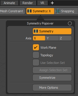
• Symmetry - toggles the symmetry function on or off; the button is highlighted in orange when it is on and remains gray when off.
• Axis - choose an axis to mirror actions across X, Y, or Z. Unless defined otherwise, the origin is always across the zero axis location.
• Work Plane - enables Symmetry when using the Work Plane.
• Topology - allows Symmetry to work in cases where regular symmetry fails by using a topological matching of components. To use this option, the target model should still be mostly symmetrical across the desired axis. Alternatively, you can use the Assign Selection Set option to define the symmetry axis for an object. To do this, select at least one edge of an edge loop that represents the centerline of the form, and then selecting the Assign Selection Set button to define the loop as the symmetry axis. Once defined, enable the Use Selection Set option and then topological symmetry mirrors across the defined edge loop.
When using the Topology option, surfaces must still have a corresponding symmetrical element. In the case of asymmetric forms, the topological symmetry does not produce the expected result.
• Use Selection Set - aids Symmetry in finding the correct topological symmetry axis by defining an edge loop representing the centerline of the surface. To use it, first define the edge loop representing the center using the Assign Selection Set option.
Note: This option does not provide for local symmetry; the symmetry plane is still always the axis center.
• Assign Selection Set - with an edge selected, representing the centerline on a symmetrical form, you can use this option to define an edge selection set specifically named for the purpose of enhancing the topological symmetry. Once defined, the Use Selection Set option must be enabled.
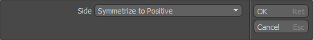
• Symmetrize - attempts to repair symmetry issues in a model, bringing models back into exact symmetrical form. Clicking Symmetrize opens the Symmetrize Vertices dialog, where you can choose the side to mirror across, either positive or negative, based on the values in the defined symmetry axis (values are based on either side of the axis center location, either positive or negative).
• More Options - opens the Symmetry Options dialog window, containing some less used Symmetry options.
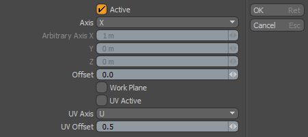
• Active - enables/disables the Symmetry function.
• Axis - choose which planar axis that Symmetry works over, or select Arbitrary to define your own custom axis.
• Arbitrary Axis - the symmetry axis is defined by a vector and center position. Arbitrary Axis allows you to set a custom axis vector.
• Offset - defines a symmetry position away from the origin, parallel to the base symmetry plane.
• Workplane - when enabled, Symmetry respects the Work Plane.
Note: If the Work Plane position is modified, the mesh must still have corresponding symmetrical geometry.
• UV Active - enables/disables the application of symmetry in the UV Viewport
• UV Axis - choose which axis that Symmetry works across. U is vertical, V is horizontal.
• UV Offset - defines a symmetry position away from the UV origin.
Tip: In certain instances of extreme asymmetry on a model, a quick and dirty way to make certain a model is symmetrical is to simply delete half of the model (making sure symmetry is disabled for this operation) and then use the Mirror command with the Specifying Action Centers and Falloffs set to Origin.
Procedural Symmetry
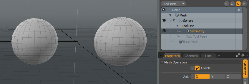
Modo provides a procedural Symmetry sub-tool that is compatible with a subset of the mesh operations in the procedural workflow including primitives and the Curve Extrude. The Symmetry tool can be added to the Tool Pipe using the (Add Tool Pipe) button in the Mesh Operations List. You can then set the Axis property to select the axis through which the tool is to be mirrored.
An example of the Symmetry tool with a procedural Primitive can be seen below. A single sphere has been added to the list, and a Symmetry tool has been added to the sphere's tool pipe. The Axis property is set to X. A translation of the sphere along X shows how the sphere is being mirrored in the YZ plane.