B-Spline Extrude
The B-Spline Extrude tool allows you to quickly extrude a geometry along the B-Spline curve.
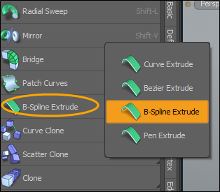
The Toolbox tools displays the last tool used. To active the B-Spline Extrude tool, open the Duplicate sub-tab in the Toolbox, right-click on the dropdown arrow on the current tool listed under the Extrude tools. From the menu, select B-Spline Extrude to view the tool options.
Using the Tool
The following examples demonstrate how this tool can be used.
Applying the Tool to a Mesh Item
In this example, there is no pre-existing curve to start with. We add a Plane primitive and then drawn a curve using the B-Spline Extrude tool.
To apply to an existing mesh:
| 1. | Open the Model layout. |
| 2. | In the left panel, open the Basic sub-tab, and Shift + click |
| 3. | Activate the Polygons selection mode or Items selection mode and select the Plane. |
| 4. | On the left panel, open the Duplicate sub-tab, and click B-Spline Extrude. |
| 5. | In 3D Viewport, click a number of times to draw a curve. |
Tip: Alternatively, change B-Spline Path options while tool is active to position the points of the curve.
The polygon selected is extruded along the B-Spline curve. Click the image below to view an animation.
Applying the Tool Using Separate Mesh Ops Item Layers
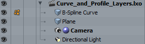
In this example, we add a Curve and Mesh item to our scene. Each have their own layer in the Mesh Ops List. The Mesh item is used to create a profile along the curve created by the B-Spline Extrude tool.
| 1. | Open the Model layout. |
| 2. | On the left panel, open Curve sub-tab and click B-Spline. |
| 3. | Click a number of time in the 3D Viewport to draw a B-Spline curve. |
| 4. | On the right panel, under Items, rename this layer B-Spline Curve. |
| 5. | On the right panel, under the Items tab, click Add Item. |
| 6. | On the left column, click Items and then double-click Mesh. |
A separate mesh layer is added to your scene.
| 7. | On the right panel, under Items, rename this layer Plane. |
| 8. | On the left panel, open the Basic sub-tab, Shift + click |
Two separate layers display in the Items tab.
| 9. | On the left open the Duplicate sub-tab and click B-Spline Extrude. |
| 10. | Click in the 3D Viewport. |
The plane is extruded along the B-Spline curve.
| 11. | Click and drag the last vertex on the B-Spline curve. |
The extruded profile updates. Click the image below to view an animation.
Applying the Tool Using One Mesh Ops Item Layer
In this example, we add a Curve and Mesh item to our scene and they are in same layer in the Mesh Ops List. The Mesh item is used to create a profile along the curve created by the B-Spline Extrude tool.
| 1. | Open the Model layout. |
| 2. | On the left panel, open the Basic sub-tab, and Shift+click |
| 3. | Activate Polygon selection mode and select the Plane. |
| 4. | On the left panel, open the Curve sub -tab and click B-Spline. |
| 5. | Draw the Curve in the 3D Viewport. |
Notice on the right panel, under the Items tab, both the Plane and the Curve are in the same Mesh Ops layer.
| 6. | Press the spacebar twice to drop the tool and selection. |
| 7. | Select the curve in the 3D Viewport. |
| 8. | On the left panel, open the Duplicate sub-tab, and click B-Spline Extrude. |
| 9. | Click in the 3D Viewport. |
The Polygon is extruded along the curve.
| 10. | Click and drag the last vertex on the B-Spline curve. |
The extruded profile updates. Click the image below to view an animation.
B-Spline Options
The following options are available:
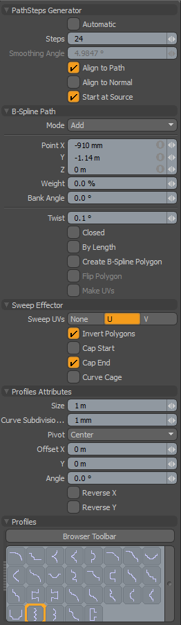
|
PathSteps Generator |
|
|---|---|
|
Automatic |
Forces a computed number of clones, based on the Smoothing Angle value, such that a clone is placed along the path to maintain a level of smoothness at or above the user-set level (determined by the Smoothing Angle). |
|
Steps |
Active only when the Automatic option is disabled. The defined Steps value determines the number of particles generated along the curve path that feed into the Effector, essentially controlling the number of segments of the resulting extrusion. |
|
Smoothing Angle |
Determines the angle along the curve where a clone is created when the Automatic option is enabled. |
|
Align to Path |
When enabled, the generated particles include rotation information so the newly-created clone aligns to the path vector direction at the location where it is created. |
|
Align to Normal |
When enabled, the generated particles include rotation information so the newly-created clone aligns with any stored normal direction for a vertex, such as for a curve extracted from geometry. |
|
Start at Source |
Often a curve used for cloning has its initial control knot imperfectly aligned with the geometry to be cloned. With Start at Source active, the curve is used as a relative guide using the original geometry as the true starting location. Disabling this option may cause the newly-created geometry to move away from the intended original location. |
|
Curve Path |
|
|
Mode |
By default, this is set to Add. In Add mode, clicking on a curve point and dragging edits the curve's position. Clicking anywhere in the 3D viewport other than the handles creates a new curve control point. To avoid creating new control points when dragging existing points around, you can set this mode to Edit. The Delete mode allows quick removal of control points by simply clicking them. |
|
Point X/Y/Z |
The XYZ position of the currently-selected knot. You can interactively edit the position by clicking over the knot indicated by the cyan dot. It turns yellow and you can now drag its position around in the viewport, or manually enter a position by editing any of the data fields. |
|
Bank Angle |
For each path position, a bank angle can be defined that controls the rotation angle of elements cloned through that position. |
|
Twist |
Works just like the Bank Angle option, but instead of being calculated per knot, the rotation amount is defined across the entire length of the curve, where the Twist value represents the amount of twisting rotation from the first knot in the curve to the last knot. |
|
Closed |
Causes the curve to become a closed loop, connecting the end point to the start. |
|
Start Control |
Enabling this toggle causes the first knot in the curve to become a control point, but not an actual segment of the curve. This provides a simple method for changing the curvature at the start of the curve. |
|
End Control |
Enabling this toggle causes the last knot in the curve to become a control point, but not an actual segment of the curve. This provides a simple method for changing the curvature at the end of the curve. |
|
By Length |
Forces the newly-created geometry to be evenly distributed across the entire length of the curve rather than spacing based on the control knots. |
|
Create B-SplinePolygon |
Generates a b-spline curve polygon with the path. |
|
Flip Polygon |
Inverts the faces of the generated polygons. |
|
Make UVs |
When this toggle is active, the tool populates the current UV map with data for the generated polygons. |
|
Sweep Effector |
|
|
Sweep UVs |
Allows you to choose between the U or V axis when placing UV data for newly-created geometry. |
|
Invert Polygons |
Reverses the normal facing direction of the polygons generated by the extrusion. This is useful when extruded geometry appears inverted or inside-out. |
|
Cap Start/End |
Forces the back end of the extruded geometry to be capped or closed. |
|
Profile Attributes |
|
|
Size |
The size of 1D or 2D profile to sweep. If the size is 0.0, it uses the real size. |
|
Curve Subdivision Tolerance |
This is the minimum angle when it subdivides the Bezier curve to a string of two-point polygons for extrusion. This setting basically controls the detail tolerance of the conversion from the original curve to the resulting polygon extrusion. |
|
Pivot |
Specifies the pivot position of the profile. |
|
Offset X/Y |
The offset amount on the profile space. |
|
Reverse X/Y |
Reverses the selected profile to horizontal or vertical. |
|
Profiles |
|
|
Profiles |
A mini Preset Browser for viewing various profiles. Works the same way as the standard Preset Browser. Selecting any of the various profiles modulates the extrusion width with the selected shape over its length. To return to the original polygon selection for the extrusion, Ctrl+click the selected profile to deselect it. |