Lace Geometry
The procedural Lace Geometry tool draws a tube along the path of a curve. By default, the tube cross section is circular, but you can also select from oval, square, rectangle, or a custom profile. The custom profile is drawn in a separate mesh, and is added to the Lace Geometry using the Profile Shape input.
Note: The tool was given its name as it was originally developed to draw the laces for a footwear modeling project.
Using the Lace Geometry
Lace Geometry requires a curve to draw along. This should be drawn in a separate mesh and added to the Guide Curve input. You can then select the cross-section shape in the Properties panel. To use a custom shape, draw one in a separate mesh and add it to the Profile Shape input.
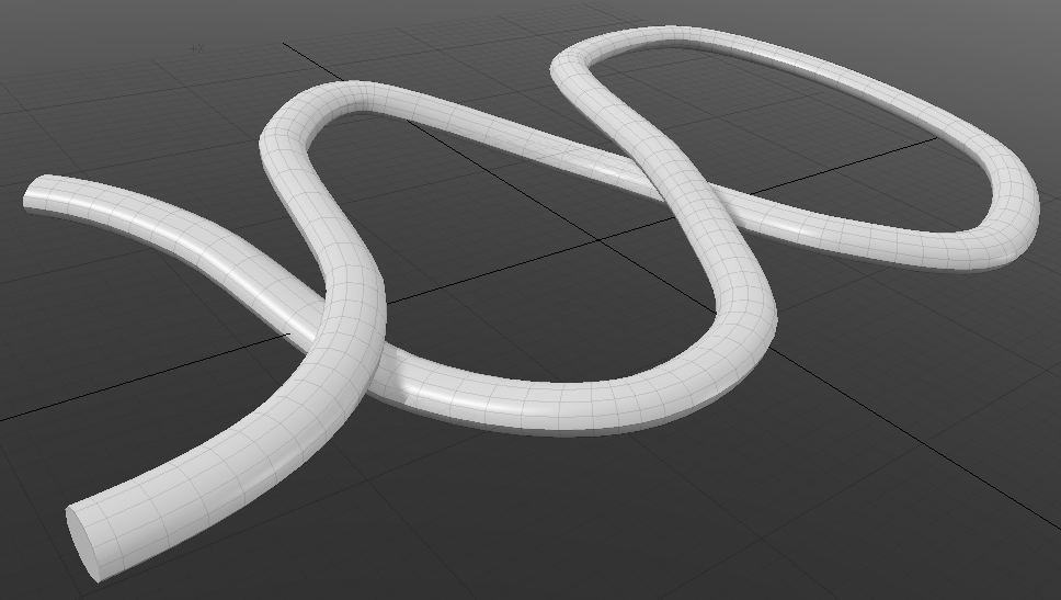
The following steps show you how to draw the mesh pictured above. In this example, the curve is drawn after the Lace Geometry is added, though this is not compulsory. The steps assume you are starting with a new, empty mesh.
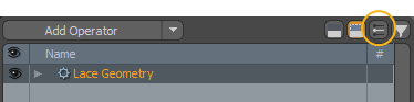
| 1. | In the Model layout, open the Mesh Ops tab and click the Add Operator button (above the Mesh Operations List to open the Procedural Preset Browser. |
| 2. | Select Mesh Operations > Duplicate and double-click Lace Geometry. |
| 3. | Set the tube width to be larger, similar to the one in the image above: In the Properties for the Lace Geometry (lower-right), set Radius to 100 mm. |
| 4. | Ensure the Mesh Operations list is not in single item view mode: if the single item view |
| 5. | Now add a new mesh to hold the curve: Click the Add Operator button, select Mesh Operations > Other and double-click Mesh. In the Item List, rename this mesh to Curve. |
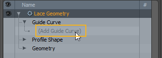
| 6. | In the Mesh Operations list, expand the Guide Curve setting for the Lace Geometry and click (Add Guide Curve). |
| 7. | Select Existing and double-click the mesh named Curve. |
| 8. | Select the Curve mesh in the Items List so that you can draw into it. |
| 9. | In the Basic section of the modeling toolbox (upper-left of the UI), select the Curve |
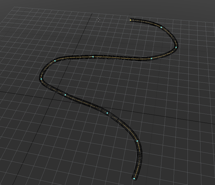
| 10. | Draw the curve in the 3D viewport by clicking at each plot point. |
The tube draws along the curve.
Note: With the default viewport settings, the tube is drawn wireframe as it is in the same mesh as the Lace Geometry, and not the currently selected Curve mesh. You can change how inactive meshes are drawn in the 3D Viewport Properties section of the 3D viewport settings. To open the settings, press O when the mouse is over the 3D viewport.
| 11. | The image at the start of this topic shows a tube with an oval cross section. You can replicate this by adjusting the properties: Select the Lace Geometry in the Mesh Operations list, and select the Lace Geometry sub-tab in the Properties panel. Change Shape to Oval and set the Aspect Ratio to 50 %. |
You can now adjust the properties to further customize the mesh.
Lace Geometry Properties
The Lace Geometry can be modified using the following properties:
|
Lace Geometry |
|
|
Shape |
The profile shape (cross-section) of the tube. Select from: • Circle - You can adjust the number of sides using the Sides property. • Oval - The height of the oval can be adjusted using the Aspect Ratio property. • Square - A square with a single edge per side. • Rectangle - The height of the rectangle can be adjusted using the Aspect Ratio property. • Custom Profile - Allows you to use any curve shape for the cross-section. Add a curve to a different mesh and then attach it to the Lace Geometry using the Profile Shape input. See Lace Geometry Procedural for more details. |
|
Sides |
Sets the number of sides when the Shape is Circle or Oval. |
|
Aspect Ratio |
Sets the relative height when the Shape is Oval or Rectangle. |
|
Radius |
Sets the radius of the tube shape. This applies to all shapes. |
|
Shape Angle |
The angle of rotation of the profile shape in 2D space before it is applied to the lace geometry. |
|
Refinement Angle |
This is the threshold when dividing the curve for adaptive subdivision. Smaller values generate more segments. |
|
Start |
The proportion of the curve length along which the tube should start. |
|
End |
The proportion of the curve length along which the tube should end. |
|
Guide Curve ID |
The index of the curve to use as the guide. This is useful if there are multiple curves in the curve mesh, and you want to select a particular one. Curve indices start at 0 and increment for each curve drawn. |
|
Pattern Size |
This is the size of UV texture and is mapped to 0-1 in UV space; this corresponds to the size of the mesh in the 3D viewport. For example, if you had a straight rectangular tube that was 2 m in length, you would set the Pattern Size to 2 m so that the sides of the tube would fit in the 0-1 UV space. Since any UVs of the Lace Geometry are procedural, it is important to set the appropriate value to make the UV texture with real size. You can see the effect of this property by opening the UV map in the UV editor and adjusting the value. |
|
Make UVs |
Sets the direction of the lacing UVs. To disable UV map creation, set this to None. |
Using the Guide Tool
The Guide Tool in the Lace Geometry operation's Properties panel gives you further control over the laces. You can reposition the points of the curve and have the laces follow the new positions, twist, or shrink the laces around a selected point.
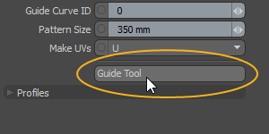
| 1. | Activate the tool by clicking the Guide Tool button. |
The tool automatically finds the lace guide curve and its points become editable in the 3D viewport. At the same time, the Lace Adjustment options appear on the left panel.
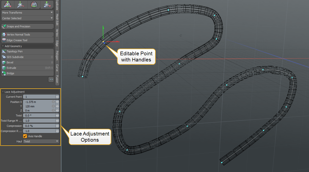
| 2. | Adjust the curve positions by clicking a point in the 3D viewport and dragging the axis handles. |
The lace geometry follows the new curve positions.
| 3. | Edit the Lace Adjustment options on the left panel. |
The following options are available:
|
Current Point |
The point selected in the 3D viewport. |
|
Position X/Y/Z |
The current point's position. |
|
Twist |
Rotates the lace along the tangent direction around the curve point. The influence range is determined by the radius. |
|
Twist Range Multiplier |
Increases/decreases the Twist's influence range. |
|
Compression |
Shrinks the lace around the curve point. |
|
Compression Range Multiplier |
Increases/decreases the Compression's influence range. |
|
Axis Handle |
Enables/disables showing axis handles for the selected point in the 3D viewport. |
|
Haul |
Specifies the hauling behavior. Clicking and dragging in the viewport with a point selected twists or compresses the lace around the selected point. |
Lace Geometry Procedural
The Lace Geometry operation has the following procedural inputs:
• Guide Curve - Set this to the mesh that contains the guide curve. If the mesh contains multiple curves, use the Guide Curve ID property (see above) to select the required curve.
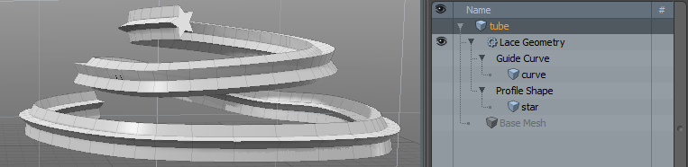
• Profile Shape - Allows you to add a custom shape to use as the profile shape. This input is used if you set the Shape property to Custom Profile. To use this input, add a profile curve to a separate mesh, click (Add Profile Shape) and select the mesh.
The image below shows a mesh generated using the Star primitive, together with the corresponding mesh operations.
• Geometry - This lists any geometry that is affected by the tool. Meshes are connected automatically if they are below the tool in the Mesh Operations list. You can connect additional meshes by clicking (Add Geometry) to open the Preset Browser. From there you can select an existing mesh or add a new, empty mesh.
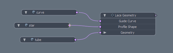
Lace Geometry Schematic
The Lace Geometry schematic node has the same inputs as the procedural version. The Profile Shape input is optional.