UDIM Workflow
UDIM is an enhancement to the UV mapping and texturing workflow that makes UV map generation easier and assigning textures simpler.
At its core, UDIM is simply an automatic UV offset system that assigns an image onto a specific UV tile, which allows you to use multiple lower resolution texture maps for neighboring surfaces, producing a higher resolution result without having to resort to using a single, ultra high-resolution image. In order to understand the benefits of the UDIM workflow, it's best to have a basic understanding of how UV mapping works.
UV Mapping Basics
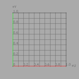
UV mapping is the translation of a three-dimensional surface into the two-dimensional coordinate system of flat bitmap images (or vice-versa depending on how you look at it). Each vertex of the originating surface is given a coordinate on the UV map, and the pixel values in-between are interpolated across the flat polygon surface for highly accurate texturing control (with the U and V axes names chosen specifically as to not cause confusion with the X, Y, and Z axes for the actual model). The UV map coordinate values are organized into a grid system, where the image itself appears in the 0-1 area of the grid and the area outside of this tile simply repeats the image outward. Because of this fact, traditionally only the UV 0-1 space was ever really used (well, outside of controlling how a surface tiled an image).
UDIM Basics
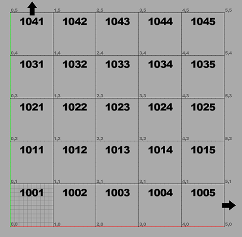
With a UDIM workflow, each whole tile section, 0-1, 1-2, 2-3, and so on, can have its own independent image map assigned to it, all within the same surface. Each image can have its own resolution as well. The UDIM workflow is simply a notation format that names images accordingly, so they are automatically assigned to a specific UV tile. The numbering starts at the UV origin and moves in the positive direction outward ten tiles (to 1010), it then repeats the rows stacked on top of each other, moving upward 9999 rows. This illustration demonstrates a small section of the overall UDIM tile area, as it relates to the UV space (the upper image corresponding to the lower-left corner of this one).
Mapping Your Model
Using a UDIM workflow begins with the UV mapping of the actual geometry. Decisions are made at this stage as to how the model is divided, typically based on what degree of resolution is required for the project. For an average character project, the tiles could be broken up into the head in one tile, the front of the body on another, and the back on another still. Higher resolution requirements might necessitate having hands and feet on separate tiles as well. For information on Modo's UV mapping tools, see the Working with UV Maps or the UV Mapping topic.
For individual parts, it's easiest to create and adjust the initial UV map for a given section in the UV 0-1 tile as many tools default to this locale. Once the map is laid out as desired, it can be moved with the Transform tool (W keyboard shortcut) to the desired UDIM tile. When working in the UV interface layout, it's easiest to simply enter whole number UV values to offset to a specific location, for example U 4.0 and V 3.0 for UDIM 1035, though it's most economical to keep the tiles consecutively placed, but never spanning more than ten tiles in any horizontal row.
The UDIM Indicator tool helps you move geometry to a UDIM tile. You can use the arrows on the indicator to shift the position of the selected geometry. The tool provides a range of useful features to help when UV mapping with UDIMs.
Creating UDIMs Using the UDIM Wizard
UDIM texturing requires a set of images to use as tiles across the UV map. You may already have these images, or you may need to build them from scratch. For the latter, Modo provides a UDIM creation wizard to automatically generate a set of blank, colored tiles that may be customized later using Modo's tools or an external editor. The wizard let's you define key characteristics such as the UDIM image range, image resolution, image format, and color. The resulting tiles are grouped into a clip group in the Images/Clips List.
To Use the UDIM Wizard
To create a UDIM group using the wizard, use the (new udims) option from the menu under the Add Clip button. You can do this by:
• adding it as a layer in the Shader Tree
The steps below show you how to generate the UDIMs in the Clips List.
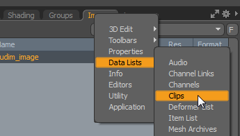
| 1. | Open the Clip Browser. By default, the Clip Browser is found under the Images tab. Alternatively, click + next to the viewport tabs and select Data Lists > Clips. |
| 2. | Click Add Clip and select (new udims). |
This opens a directory browser.
| 3. | Browse to the directory in which to create the UDIMs, and click Select Folder. |
The file browser closes, and the UDIM Wizard opens.
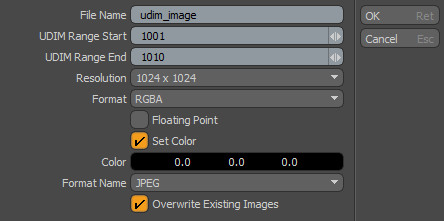
| 4. | Edit the fields in the UDIM Wizard as required: |
|
UDIM Wizard |
|
|
File Name |
The base file name for the created UDIM images (tiles). The UDIM images are named in the format: [filename]_[UDIM number].[format extension] |
|
UDIM Range Start |
The first UDIM tile number in the range. |
|
UDIM Range End |
The last UDIM tile number in the range. |
|
Resolution |
The resolution of each tile. |
|
Format |
Defines the color format of the tiles. Choose from: • Gray - Grayscale. • RGB - Opaque RGB color images. • RGBA - RGB color images with an alpha channel to support transparency. |
|
Floating Point |
Choose whether to use floating-point values or not for the image. Floating point images (also known as HDRI, High Dynamic Range Images) give a broader range of potential color values. By default, this checkbox is off, and Modo creates an integer image that defines colors in 8 bits per channel (0 to 255). A floating point image can use many more values, and are useful for light sources or for detailed displacement maps. |
|
Set Color |
Choose whether or not the image has a base color, or base transparency, to start. If Set Color is off, new images are completely blank (with no color or alpha pixels). If Set Color is on, each RGBA image has an opaque alpha (100% so all pixels are visible) and a base color as specified in the Color option. |
|
Color |
The base color of each tile. |
|
Format Name |
The image format used for the tiles. |
|
Overwrite Existing Images |
Check this to overwrite any images of the same name in the target folder. |
| 5. | Click OK to generate the images. |
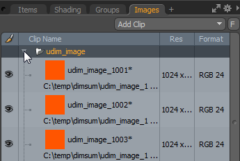
The clip group is added to the Clip List.
| 6. | Open the clip group to inspect the tiles. |
Note: You can also generate a clip group in the Shader Tree using the (new udims) option.
Creating UDIMs Manually
As an alternative to using the UDIM wizard, multiple UDIMs can be imported from an external painting app (such as Mari) or created one-by-one in Modo. This is done as follows:
| 1. | Make an image folder. |
| 2. | Import or create the images. |
| 3. | Set the UDIM properties. |
To Make an Image Folder
You need to make a new folder to hold a set of UDIM images. Click on the Images (or Clips) tab. This tab is typically found in the same viewport group as the Shader Tree viewport. Click the Add Clip button and choose the (new image folder) option.
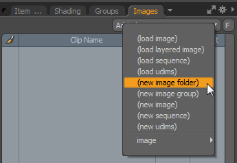
This action creates a folder in the Images viewport.
Note: The Images tab and the Clips tab show the same viewport. Depending on your set-up, you may only see the Clips tab.
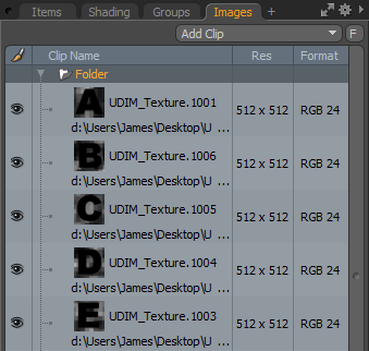
To Import UDIM Images
Select the new folder in the Clips tab, and use the (load Image) option to import multiple images from a single location, or singly import images from multiple locations. You can also drag-and-drop images into the image group folder.
To Create a UDIM Image Manually
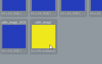
Instead of importing images, you can use the (new image) option to create blank images. Each image needs to be manually named according to its UDIM tile location. Make sure to adhere to a proper naming convention:
<filename>.<UDIM value>.<format extension>
For example, hero_wings_diffuse.1012.EXR
Tip: You can rename the folder if required.
The next step is to assign the proper UDIM values to each bitmap image.
To Set UDIM Properties
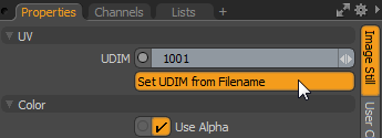
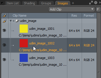
In order to use the images as UDIMs, each file must have its UDIM property set. This holds the position of the UDIM tile using the UDIM numbering scheme. You can set this property on all images at once using the number in their file name.
| 1. | Select all the images within the folder: click the top-most image to select it, then Shift+click the image in the bottom layer. |
| 2. | In the Properties viewport, under the Image Still sub-tab, click the Set UDIM from Filename button to assign the values automatically. |
Now the clip folder is ready to be applied to a surface.
Texture Mapping
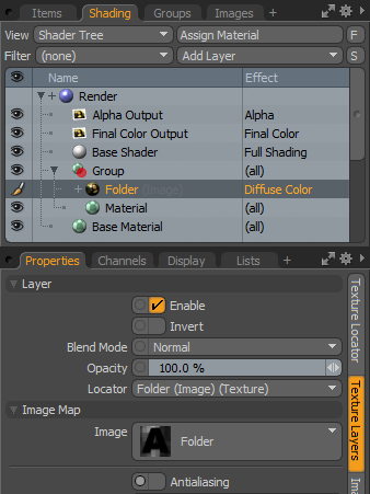
All the images in a UDIM folder can be assigned to a surface in the Shader Tree as a single layer.
| 1. | In the Shader Tree, click the Add layer button and select Image Map > (use clip browser). |
The Clip Browser opens.
| 2. | Select the UDIM folder. This appears as a single icon, labeled with the images' prefix. |
Note: Please refer to the Adding Images topic for information about adding and using texture maps, and the Shader Tree topic for information on working with Shader Tree layers.
If your textures aren't visible, it may be necessary to check that the correct UV map is specified in the associated Texture Locator.
Note: For older models it may be necessary to make sure the Use Clip UDIM option is enabled.
Once assigned with the proper Effect type, it is ready for rendering. Or, if this is the beginning of the process, then it is ready for texture painting or baking.
 \
\
Tip: Each folder that is assigned to the Shader Tree using the steps above, can only have a single layer Effect (such as Diffuse Color or Bump). Individual images within a folder can't have their own unique Effect setting. And so it's important to make sure that the images are arranged into their own folders, with a folder for each Effect type.
Viewing the UDIM Tiles on the UV Map
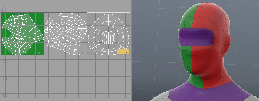
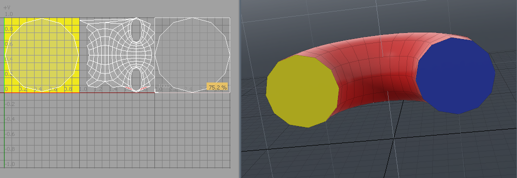
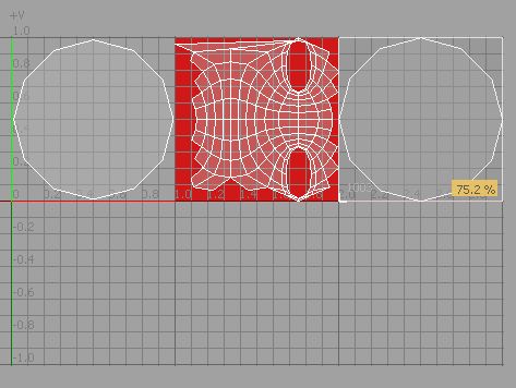
When UDIMs have been added to a material on the Shader Tree, you can see the position of the UDIM tiles in the UV map viewport. The image below shows a simple mesh that has been UV mapped using three UDIM tiles, each of a different color.
Tip: The UV viewports shows the 0 to 1 space by default. The UDIM tile number display is enabled by default but it is only shown if more than the 0 to 1 space is shown.
Note: The UV viewport in the image below shows a UV area with U High Span of 3, to cover the three UDIM tiles. This can be adjusted in the UV Viewport Properties window, which is opened by pressing O when in the UV Viewport.
| 1. | Click on the UVEdit tab to open the UV Map viewport. |
| 2. | Open the Clips List and click on a UDIM image. |
The image displays on the UV map.
UDIM Baking
If you're using UDIM placement in your UV map, you can bake each tile to a separate UDIM image. For more details, see Bake to UDIM Tiles.
Mari Workflow
Modo's UDIM automation options really shine when working with an external texturing application, such as Mari, where image map UDIM naming is automatic. When working on complex models, where there are possibly hundreds of images associated with it, this is definitely the way to go as Mari saves the images directly, then Modo imports entire folders of images and assigns the UDIM offset values automatically, based on the file names from Mari.
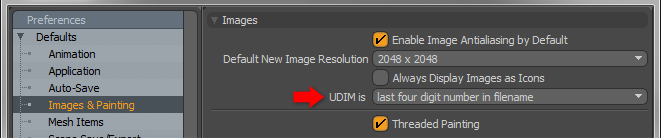
When working with Mari specifically, make sure the Preferences option for UDIMs under the Defaults > Images and Painting menu is set as last four digit number in filename. This ensures that the filename UDIMs are read properly when imported.
Loading an entire folder of images saved in Mari into an Image Folder in Modo and setting the UDIM values for each image is done in one operation. In the Images viewport panel, select the Load UDIMs option.
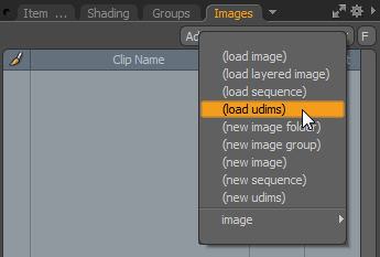
This opens an OS-specific dialog where you can navigate to any folder of UDIM images and multi-select all the associated images and press the Open button. This loads the images into an image group "Folder" and specifies the UDIM value for each automatically. The image can now be assigned in the Shader Tree like any other texture layer.