Using the Work Plane
Using a flat screen to create and edit content in 3D space can sometimes feel awkward and unnatural. Software has tried to resolve the disconnect using different solutions over the years.
The most popular is the four viewport method. Each orthogonal viewport only provides two axes at any given time, eliminating surprises as you create and modify geometry in a given scene. Another solution is working with tool handles constraining operations performed in a perspective viewport to the same flat 2D axes of the four viewport method. Both of these solutions are reasonable and available in Modo. However, Modo also employs a third method called the Work Plane.
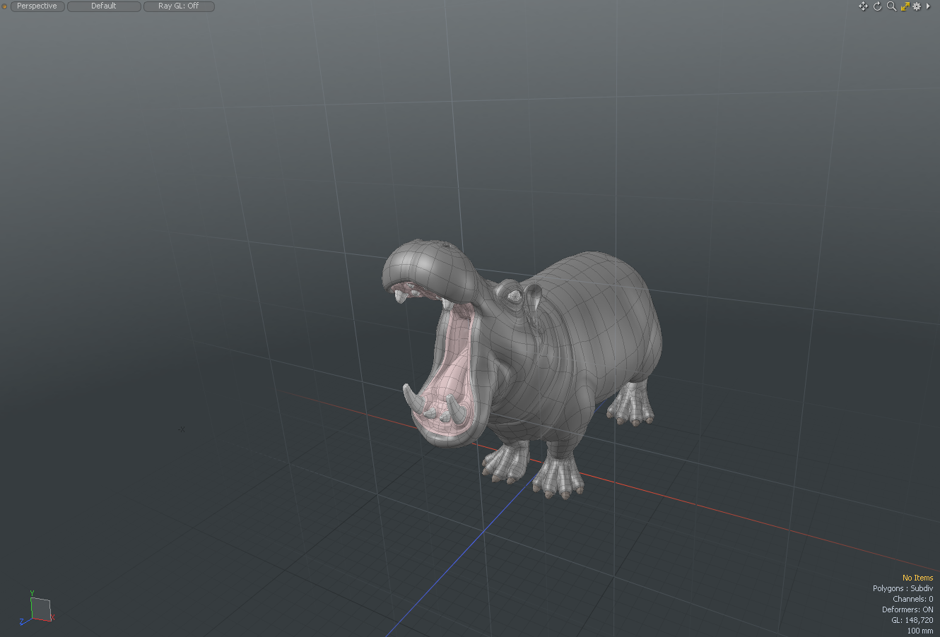
The Work Plane is a white grid that appears in the 3D viewports. It is an adaptive modeling aid that automatically adjusts itself to match the two major axes most closely aligned to your current screen axis, represented by a white grid in any of the 3D viewports. When you rotate the Perspective viewport, the Work Plane snaps to one of the dominant planes, XY, XZ, or XY. Action Centers often use the Work Plane position to determine the center and axis of tools when activated. When hauling, many tools also use the Work Plane to determine the axes of operation when this information cannot be derived from a specific tool handle.
While the default mode for the Work Plane is to automatically adjust to the screen's orientation, it can also be locked and used as a construction plane. When applied as such, the Work Plane effectively positions the entire Modo universe to that fixed angle and position. There are a number of methods for manually setting the Work Plane to a specific center and axis. The Work Plane can be easily locked to a specific major axis and position, or you can snap the Work Plane to selected geometry or even just to the polygons directly under the mouse. This level of flexibility and control provides you with a fluid and rich set of options for editing your workspace.
Mastering the Work Plane allows you to do most, if not all, of your modeling in a single perspective viewport. That means more screen space remains for viewing the geometry and performing the various modeling tasks, allowing you to work more fluidly and accurately. Experiment with the Work Plane when using tools and hauling, so you can get a better grasp of its behaviors and use it to your advantage.
To apply the Work Plane:
| 1. | In the 3D viewport, make your selection. |
| 2. | Under the interface layout tabs, click Work Plane. |
The Work Plane is immediately aligned to what you had selected in the 3D viewport. The Work Plane button is now displayed in orange to indicate that it is active.
Tip: You can quickly offset the position of the Work Plane using a keyboard shortcut. Hover the mouse over some geometry in the scene where the Work Plane should move to, then press Alt+O. The Work Plane retains its orientation but moves to the location where the mouse pointer intersects with the geometric element.
Work Plane Controls
The Work Plane is a persistent function of the 3D viewports, and is visible by default in the menu below the interface layout tabs. You can toggle its display under the Visibility tab of the 3D viewport Properties panel. To open it, hover the mouse over a viewport and press the O key. Additionally, you can toggle the Work Plane visibility by pressing the * (asterisk) key on the number pad.
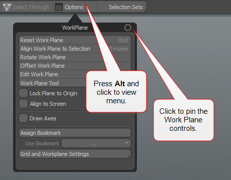
The controls for the Work Plane are displayed by pressing Alt + Work Plane, or by clicking Edit > Work Plane. You can also use the Home key to dynamically position the Work Plane to any geometry directly under the mouse pointer, centering under where the pointer tip intersects the polygon's surface and aligning it to the polygon's normal direction.

Tip: To pin the Work Plane control options dialog box, hold down the Alt key + click WorkPlane and then click the circle on the top right corner. To reposition the dialog box, click-and-drag it to a new position on the viewport.
Reset Work Plane
This command returns the Work Plane to its default behavior. It only applies if the Work Plane has been aligned as a fixed construction plane.
To reset the Work Plane:
• Under the interface layout tabs, click Work Plane.
The Work Plane is reset back to its original default position and its button is now displayed in gray to indicate that it is not active.
Align Work Plane to Selection
Aligns the Work Plane to the current component selection as described below. If nothing is selected, the Work Plane is aligned to the average normal of all foreground polygons.
To activate the command, click Edit > Work Plane > Align to Selection. Alternatively, Alt+click on the Work Plane button on the menu bar and select Align Work Plane to Selection.
When selecting vertices:
• If a single vertex is selected, only the center of the Work Plane is changed.
• If two vertices are selected, the first vertex sets the center and the Work Plane is altered to align the Z axis with the second vertex.
• If three vertices are selected, it uses the first vertex to set the center, the second to set the Z axis and the third defines the XZ plane.
• If more than three vertices are selected, the center is located at the average of their positions, and the plane is angled to put all vertices as close as possible to the XZ plane.
When selecting edges:
• If a single edge is selected, it is treated the same way as two vertices using the ends of the edge (above).
• If two edges are selected, they are treated the same as three vertices (above).
• If three or more edges are selected, this results in the same solution as vertices, using the end points of the edges as the vertices
When selecting polygons:
• If a single polygon is selected, the Work Plane is centered on that polygon with the Y axis aligned to the polygon normal. The longest edge of the polygon is along the Z axis.
• If multiple polygons are selected, the average normal is along the Y axis, and the system uses a best guess to determine correct orientation.
Tip: Right mouse click over any Item in the 3D Viewport and select Set Work Plane from the contextual menu to align the work plane to the item center.
Rotate Work Plane
The Rotate Work Plane function provides a way to accurately rotate the Work Plane a defined number of degrees away from its current position.
To activate the command, click Edit > Work Plane > Rotate. Alternatively, Alt+click on the Work Plane button on the menu bar and select Rotate Work Plane.
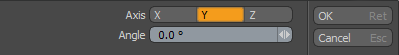
Invoking the command opens the following dialog.
|
Axis |
This option defines around which axis the Work Plane rotates, originating at the Work Plane origin (0,0,0) position. |
|
Angle |
Defines the number of degrees to rotate the Work Plane away from its home position. |
Offset Work Plane
The Offset Work Plane function provides you with a means to accurately position the Work Plane by way of an offset from its current position.
To activate the command, click Edit > Work Plane > Offset. Alternatively, Alt+click on the Work Plane button on the menu bar and select Offset Work Plane.
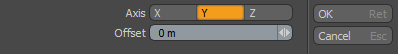
Invoking the command opens this dialog.
|
Axis |
This option defines around which axis the Work Plane offsets its position along. |
|
Offset |
Defines the distance to offset the Work Plane away from its current position. |
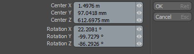
Edit Work Plane
Displays the current values of the Work Plane as offset from the true World Origin position at 0,0,0. You can edit the values to precisely position and rotate the Work Plane.
To activate the command, click Edit > Work Plane > Edit. Alternatively, Alt+click on the Work Plane button on the menu bar and select Edit Work Plane.
Work Plane Tool
The Work Plane Tool allows for interactive placement of the Work Plane itself. When combined with Snapping, the Work Plane can be placed very accurately. The Snapping tool is found in the menu bar below the interface layout tabs. Click in the 3D viewport to draw the tool handles that allow for interactive placement. The initial click places the handles at the intersection of the mouse click position and the existing Work Plane. You see the standard 3-point axes handles colored accordingly, with a small square at the center and two more at the ends of the axes pointers. The initial square at the center defines the Work Plane's center and the other two work together with the center to define a plane.
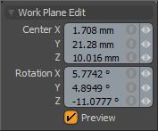
To use it, activate the tool, and then ensure that the Preview option is enabled in the tool's Properties panel. Then click in the 3D viewport, use the resulting tool handles to place the center and define the plane by clicking and dragging them in to the proper position. Numeric values on the tool's Properties panel can also be modifies to adjust the plane manually. Disabling the Preview option with the tool still active places the Work Plane, locking it to the defined location. Press the spacebar to drop the tool, allowing further editing of the scene with the newly defined Work Plane.
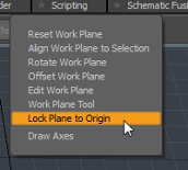
Lock Plane to Origin
The Lock Plane to Origin toggle forces the Work Plane to intersect the World Origin position at 0,0,0. The Work Plane still aligns to the facing plane, and it may appear that it has shifted away from the origin. However, when you draw an object, it aligns to the Work Plane at zero distance from the World Origin along the axis that is perpendicular to the Work Plane.
To activate this command, Alt+click on the Work Plane button on the menu bar and enable the check box for Lock Plane to Origin.
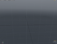
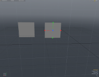
For example, if the Work Plane appears to be aligned to the XY plane and you draw a primitive, the X,Y coordinates are determined as normal, by mouse position. However, the primitive origin is placed at Z=0. In this case, the Z-axis is perpendicular to the Work Plane, and the Work Plane is positioned at Z=0 to intersect the World Origin. The images below illustrate this process.
|
|
|
|
1. The Work Plane is aligned to the XY plane, a short distance behind Z=0. |
2. A flat cube primitive is drawn. (Lock Plane to Origin is off.) |
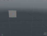
3. Lock Plane to Origin is activated. |
|
|
|
|
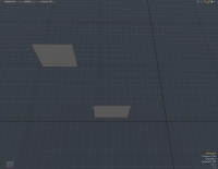
4. A second flat cube primitive is drawn. |
5. Looking overhead, notice that the second primitive is located at Z=0. |
Tip: To help draw primitives on the ground (XZ) plane, toggle Lock Plane to Origin on, and rotate the viewport so that the Work Plane aligns to the ground plane. If the primitive has a flat base, such as a cube or cylinder, draw the flat object and then extrude the height. This locates the object on the ground plane. For objects that are initially drawn in 3D, or objects with a rounded base, you need to adjust the Y-position to sit the object on the ground plane.
Align to Screen
The Align to Screen option sets the default Work Plane to the screen direction instead of a major axis plane. Primitive tools, such as Pen and Sketch, stroke point positions on a major axis plane when there is no custom Work Plane set. Align to Screen unlocks the default Work Plane from a major axis to allow the stroke points on exact screen axis plane. This is useful when you want to draw curves using Sketch on the current screen space without setting custom Work Plane.
Draw Axes
This toggle enables and disables the drawing of an axis handle widget in the viewport at the origin position of the Work Plane, making it easier to recognize the center and axis directions.
Assign Bookmark
Work Plane bookmarks can be assigned to polygons and re-used later on. Different bookmarks can be saved for each of your scenes. This is useful to store construction planes in the geometry itself. To reset your selected polygons to the origin, select Work Plane > Reset Work Plane.
Tip: The 3D viewport item contextual menu also has an option to set the Work Plane on the item, making it easier to model in item space. Right-click on a mesh item and select Set Workplane. An item Work Plane aligns to meshes that have been moved away from the world origin in Items selection mode. It aligns the Work Plane to an item's center locator.

The following options are available:
• Name - Apply a name for a new bookmark or select an existing bookmark and then select a Mode.
• Mode - Select one of the following operations to apply.
• Add - To add a new bookmark.
• Remove - To remove an existing bookmark.
• Rename - To rename an existing bookmark.
• Set - To set the current view as a bookmark.
• New Name - Rename a bookmark.
Use Bookmark
A list of previously created bookmarks, made for a particular scene, are listed. By selecting a bookmark, the polygon(s) assigned to that bookmark are fitted to the specified Work Plane.
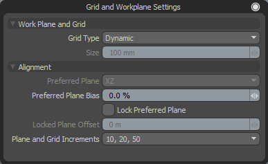
Grid and Workplane Settings
This Work Plane option allows you to specify the grid and Work Plane settings. All the settings are applied globally to all viewports and are stored inside a configuration file found in the application menu System > Open User Configs Folder.
This video shows you how to save customized settings. The same workflow applies to the current version of Modo.
Note: The Snapping option no longer controls the grid display. The Snapping tool simply allows you to accurately create and align elements in relation to one another, or in relation to 3D space. For more information, see Applying Snapping.
|
Work Plane and Grid |
|
|
Grid Type |
An option for selecting which type of grid to display in the viewport. The following options are available: • Fixed - The grid is displayed in regular intervals. • Dynamic - The grid is dynamic depending on the zoom level, a small display in the lower right corner gives you the real world equivalent measurements for each square unit. |
|
Size |
This option is enabled when the Grid Type is set to Fixed, allowing you to specify the size of the grid squares displayed in the viewport. When zooming out, grid lines can merge together when they become too small. When this occurs, Modo converts fixed grids to dynamic grids. |
|
Alignment |
|
|
Preferred Plane |
When the Preferred Plane Bias option is set above 0%, you can choose a preferred Work Plane. Based on the bias amount, Modo attempts to keep the work plane positioned at the preferred plane determined by its two major axes. |
|
Preferred Plane Bias |
When working with the Work Plane, Modo tries to keep the plane perpendicular to the viewport window when navigating and rotating the view. The higher the value set, the more the Preferred Plane setting is displayed. |
|
Lock Preferred Plan |
You can lock the Work Plane to a specific plane-facing direction by enabling this option. Once fixed, rotating the viewport does not affect the position or angle of the Work Plane. |
|
Locked Plane Offset |
When the Work Plane is locked, you can additionally set an offset from the origin, providing accurate control over the position and placement of the Work Plane when used as a construction plane. |
|
Plane and Grid Increments |
As you zoom in and out of a scene, the Work Plane grid adjusts the density of the grid divisions, adding or removing subdivisions based on the plane increments. You can modify this behavior using this option. |
Procedural Set Work Plane
Modo includes a procedural sub-tool to position and orient the Work Plane, called Set Work Plane. This can be added to the Tool Pipe input of any procedural tool that supports a Work Plane to transform its operation. Click the tool's (Add Tool Pipe) link to open the Procedural Preset Browser. Set Work Plane is in the Procedural > Tool Pipe > Sub-tools category.
If connected to a primitive tool, rotating and moving the Work Plane rotates and moves the primitive.
Procedural Set Work Plane Properties
|
Set Work Plane |
|
|---|---|
|
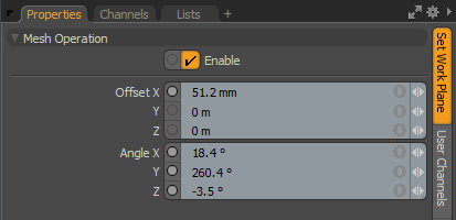
Enable |
Toggles the tool on or off. |
|
Offset X, Y, Z |
Sets the Work Plane position. |
|
Angle X, Y, Z |
Sets the rotation of the Work Plane on each axis. |