The Dynamic Replicator, when connected to a Particle Simulation and a Replicator Item, allows the spawned replicas to act like Active Rigid Bodies. This can be useful for a number of cases, such as filling up a large container of objects, or in other cases where large numbers of dynamic items are required.
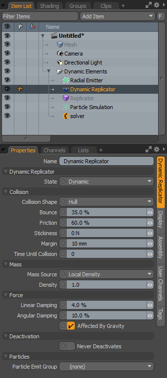
To create a Dynamic Replicator, you first need to create a particle simulation of some sort. You can use any of the various Particle Emitters available. Next, a Replicator needs to be created, this can be added in the Items list using the Add Items function under the Particles > Replicator menu. Once added, the particle simulation is designated as the Particle Source in the Replicator Item's Properties panel, and the target Mesh Item (or a group of items, for variations) designated as the Prototype option. Once defined, select the Replicator Item in the Items list and then in the Dynamics toolbox, tagged as Active Rigid Body by clicking the toolbox button of the same name. This adds a solver item (if not already present), and the Dynamic Replicator Item to the scene. Selecting the Dynamic Replicator in the Items list shows the following attributes in the Properties viewport.
|
Option |
Description |
|---|---|
|
Name |
This data field displays the current item name. Change it by clicking on the field and typing the new name. |
|
Dynamic Replicator |
|
|
State |
Determines how the spawned dynamic items are evaluated for collisions. Dynamic means that they are treated like Active Rigid Bodies, with inter-object collisions as well as collisions between other dynamic items. Kinematic means they are treated like Kinematic Rigid Bodies, no inter-object collisions between elements within the same Replicator, but they collide with other dynamic objects in the scene, acting on them much like a force does. |
|
Collision |
|
|
Collision Shape |
Defines the shape used to calculate collision contacts between both replicated elements and other dynamic objects within the scene. It is best to choose the simplest shape that produces satisfactory results. The default collision shape is set to Hull which generally balances accuracy with calculation speed. • Box: A rectangular box defined by the bounding box of the geometry's maximum extents. • Sphere: A sphere sized to encompass all the geometry of the object. • Hull: The default collision option, creates the smallest convex volume that encompasses all the points in this mesh. To visualize it, imagine the mesh enveloped in shrink-wrap. The Hull collision type does not support holes or indentations in the object. While only approximating the item's shape, it provides very fast collision detection on complex shaped objects. • Mesh: Uses the actual mesh of the object for calculating collisions. For subdivision surfaces models, the actual frozen Sub-D cage is used. Avoid this option on Dynamic Rigid Bodies (it is fine for Static and Kinematic). When used otherwise, performance, as well as simulation stability can suffer. • Convex Decomposition: Creates multiple Hulls (described above) and connects them together. This works to better approximate the actual shape of the geometry but can be costly to initially compute on complex shapes. • Plane: Generates a infinite ground plane collision shape originating from the center of the associated geometry's bounding box, not on the item's actual center position. |
|
Bounce |
This is the collision response when this object hits another dynamic object. A value of 0% means the object doesn't bounce or inherit energy from other dynamic objects it contacts. A value of 100% means the object inherits all of the energy from the contact object. Values above 100% produce rubber ball-like effects, where objects impart more energy from contacts. |
|
Friction |
The amount an object slides against another object. A value of 0.0 offers no resistance, while a value of 1.0 keeps the object from sliding entirely. |
|
Stickiness |
When two dynamic elements collide, both with Stickiness values defined, they attach to each other at the collision point. The higher the Stickiness value, the stronger the bond between the elements. Lower values allow stuck elements to be broken more easily. |
|
Margin |
This value helps the bullet engine to determine collisions, as well as improve its performance and reliability. It defines a gap around the object used to detect a collision contact. In most cases it should be kept at its default value. When used with the Mesh and Convex Decomposition settings, this can offset items away from each other, so only a small amount is necessary. NOTE: A setting of 0 (zero) may produce errors in collision detection. |
|
Time Until Collision |
This option determines the point in time from when the Replicator Item is created until when collisions are actually calculated for the object. This allows the object to spawn without causing immediate collision issues. Time is defined by frames. |
|
Force |
|
|
Linear Damping |
This is a force that acts upon the motion of objects, acting to slow them down over time. A small value here can benefit object stability, since it helps objects come to rest. |
|
Angular Damping |
Same as Linear Damping, but applies to the rotation of the object. |
|
Affected By Gravity |
Toggle gravity's global influence on or off for specific items. |
|
Mass |
|
|
Mass Source |
When the Mass Source is set to World Density, the mass of an object is calculated by multiplying the calculated volume of the dynamic item by the Global Density value defined on the Open topic with navigation item. You can override that value by setting the Mass Source to Local Density or Local Mass and expressly setting a value. |
|
Density |
The measure of the amount of matter in any given volume. If the Mass Source option is set to Local Density, this is the density value that is used. The mass of the object is determined by multiplying the computed volume by this value. |
|
Deactivation |
|
|
Never Deactivates |
When this option is enabled, the item never gets deactivated due to no motion. When disabled, the item is disabled when it meets the defined linear and angular thresholds defined in the solver item (or overridden here). |
|
Particles |
|
|
Particle Emit Group |
When a particle emit Group Item is defined (either a group of dynamic items or a single other dynamic item), the dynamic item emits a particle at the contact point when it collides with the defined item. This option requires an additional connection (in the Schematic viewport) to the dynamic collider item. |

When following the procedure outlined in the Usage section, the Dynamic Replicator Item is added to the scene automatically when the Replicator Item is tagged as an Active Rigid Body. If you prefer to work in a more Schematic-centric workflow, you can manually add the Dynamic Replicator Item to the Schematic viewport.
| 1. | Click the Items list's Add Item button. |
| 2. | Select Other > Dynamic Replicator from the dropdown menu. |
| 3. | Then drag and drop, the item to the Schematic viewport. |
| 4. | A Dynamics Solver also needs to be manually added, if not already present. In the menu bar, click Dynamics > Add Solver. Add this item also to the Schematic viewport. |
| 5. | In the Schematic viewport, connect the Dynamic Replicator to the Solver under its Dynamics input, and connect it to the particle simulation as an Operator. |
Lastly, the item or group of items needs to be connected as the Prototype on the Dynamic Replicator itself. This completes the necessary connections for a basic particle simulation. For more information on working with nodes and the Schematic viewport, see Schematic Viewport.