
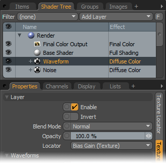
Each Enhance:Modo Waveform layer is a special type of Shader Tree layer that produces no results by itself because a Waveform layer modifies a similar texture layer below it in the Shader Tree hierarchy. For example, a Waveform layer would only affect a texture layer (such as a Diffuse layer) if the Waveform layer has its effect set to Diffuse and is above the texture layer. To affect a Displacement layer, you must change the Waveform layer's effect to Displacement as well. If you have multiple layers of the same type blended together, the Waveform layer only affects the nearest visible layer below it. Each Waveform type produces its own independent result.
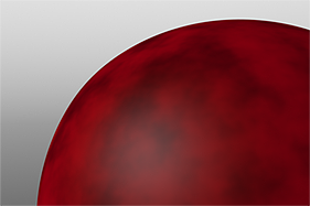
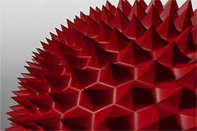
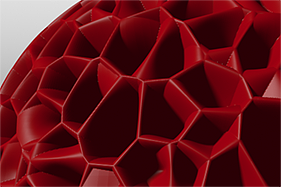
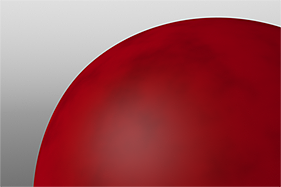
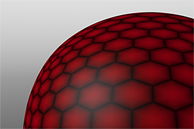
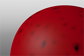
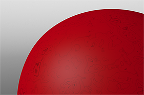
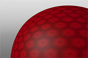
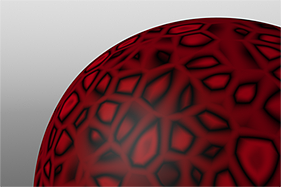
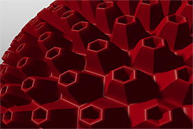
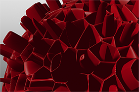
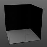
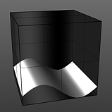
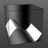
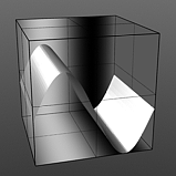
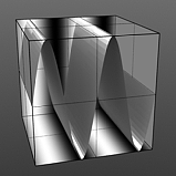
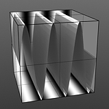
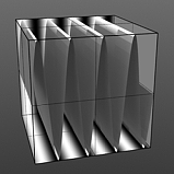
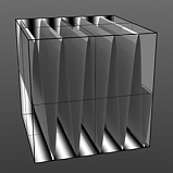
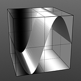
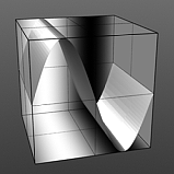
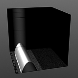
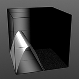
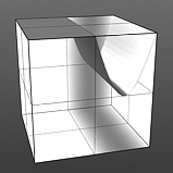
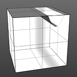
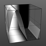
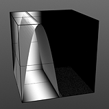
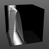
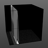
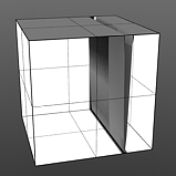
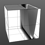
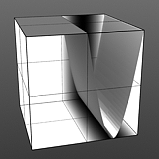
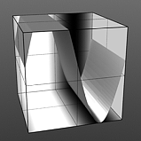
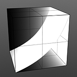
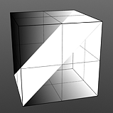
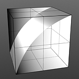
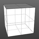
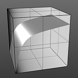
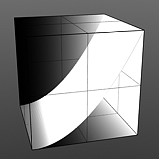
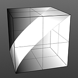
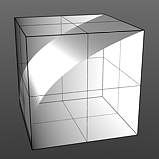
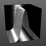
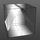
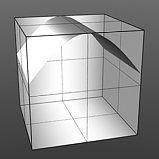
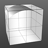
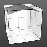
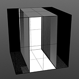
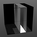
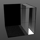
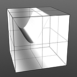
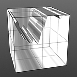
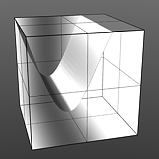
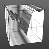
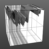
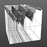
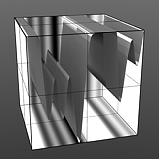
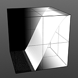
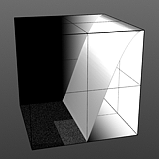
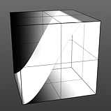
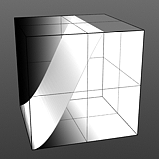
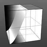
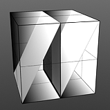
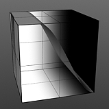
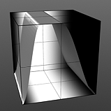
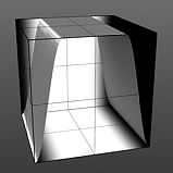
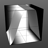
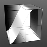
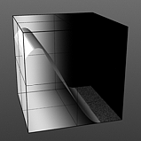
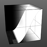
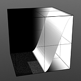
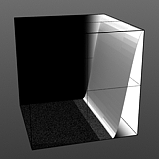
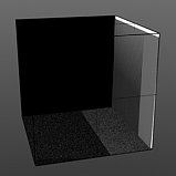
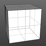
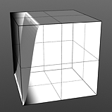
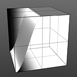
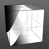
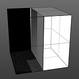
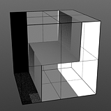
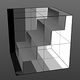
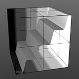
If you are familiar with Photoshop's Curves functionality, then you might find it easier to understand the Waveform function. The Waveform function is a means to manipulate the values of the texture layer (just like Curves affect values in an image). If you make a graph of the input values versus the output values of a surface, the direct correlation of the input and output shows as a straight line. As you make adjustments to the graph, the values on the graph change. These adjusted values can modify the shades of gray across a procedural texture or the shape of a displacement map. In the examples, the image on the far left shows a displaced plane with an applied gradient ramp and offset that is the same height as its width to show a ramp at a 45-degree angle. If you apply various Waveform layers to the gradient, the other images show how the Waveform layers affect the values across the gradient ramp to illustrate the shaping ability of the Waveform function.
Displaced Plane |
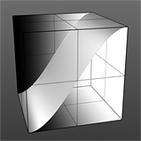
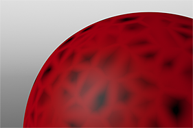
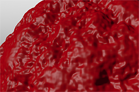
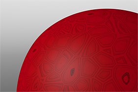
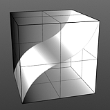
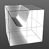
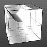
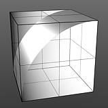
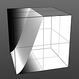
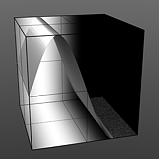
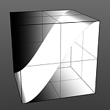
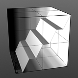
S-Curve Waveform |
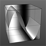
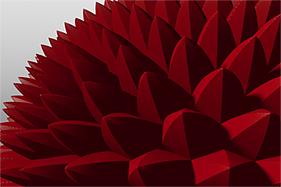
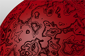
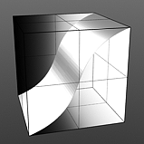
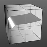
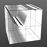
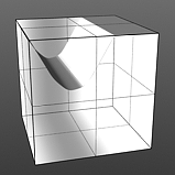
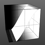
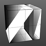
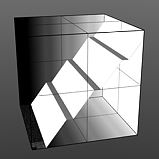
Sine Waveform |
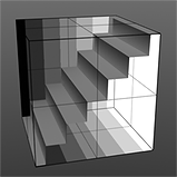
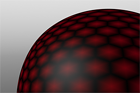
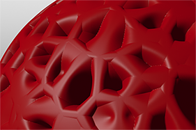
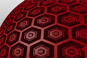
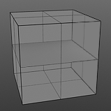
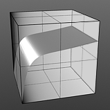
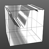
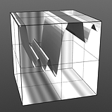
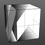
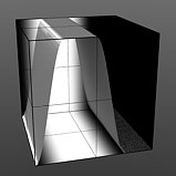
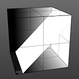
Stairs Waveform |
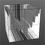
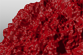
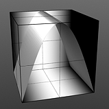
Noise Waveform |
To work add a Waveform layer, select the Material Group item (for the texture) in the Shader Tree. Then, in the Add Layer list, select one of the available waveform options (Add Layer > Enhance:Modo Textures > a waveform). For additional information about adding layers and working with Shader Tree item layers, see the Shader Tree topic. Each waveform produces its own unique results. (Generally, the waveform's name suggests how it shapes the associated layer.) You can modify the attributes of the Waveform layer in its Properties panel.
|
Option |
Description |
|---|---|
|
Layer |
|
|
Enable |
Toggles the effect of the layer on and off to duplicate the functionality of toggling visibility in the Shader Tree. When disabled, the layer has no effect on the shading of the scene. However, Modo saves disabled layers with the scene, and they are persistent across Modo sessions. |
|
Invert |
Inverts the colors (RGB values) for the layer to produce a photonegative effect. |
|
Blend Mode |
Affects the blending between different layers of the same effect type. With this, you can stack several layers for different effects. For more about blending, see the Layer Blend Modes topic. |
|
Opacity |
Changes the transparency of the current layer. Reducing this value increasingly reveals lower layers in the Shader Tree, if present, or dims the effect of the layer, itself, on the surface. |
|
Locator |
Sets the association for the Texture Locator. Most texture layers have a Texture Locator that Modo automatically creates in the Item List. This defines the mapping of the texture (how Modo applies the texture) to the surface. You can specify alternate locators, but the need to do so is rare. Still, you may want multiple texture items to share a single locator. |
|
Waveform-Specific Controls |
|
|
See below these tables for waveform-specific options and examples of those settings. |
|
|
Option |
Description |
|---|---|
|
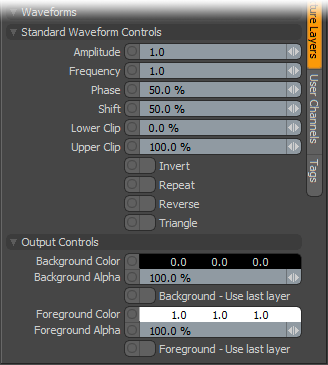
Standard Waveform Controls |
|
|
Amplitude |
Controls the maximum value of the waveform and scales all other values in relation to this maximum. Click to view examples of various Amplitude settings. |
|
Frequency |
Controls the number of waveform occurrences in a single cycle. A waveform only cycles multiple times when you enable Repeat. Click to view examples of various Frequency settings. |
|
Phase |
Moves the waveform forwards and backwards. Click to view examples of various Phase settings. |
|
Shift |
Moves the waveform up and down. Click to view examples of various Shift settings. |
|
Lower Clip |
Specifies a clip level for the Background Color to truncate values beyond the defined setting. Combined with the Upper Clip value, you can apply this option to extend or lessen the range of values for the texture. Click to view examples of various Lower Clip settings. |
|
Upper Clip |
Specifies a clip level for the Foreground Color to truncate values beyond the defined setting. Combined with the Lower Clip value, you can apply this option to extend or lessen the range of values for the texture. Click to view examples of various Upper Clip settings. |
|
Invert |
When enabled, flips the waveform vertically. |
|
Repeat |
When enabled, repeats the waveform and useful when if you set the Frequency value higher than 1. |
|
Reverse |
When enabled, flips the waveform horizontally. |
|
Triangle |
When enabled, mirrors the waveform on its own axis. |
|
Output Controls |
|
|
Background Color |
Specifies the Color of the texture's background area, which ramps toward the Foreground Color. |
|
Background Alpha |
Specifies the Alpha transparency of the Background Color. |
|
Background - Use Last Layer |
When enabled, makes the Background Color area completely transparent to reveal the shading results of lower layers. |
|
Foreground Color |
Specifies the Color of the texture's foreground area, which ramps toward the Background Color. |
|
Foreground Alpha |
Specifies the Alpha transparency of the Foreground Color. |
|
Foreground - Use Last Layer |
When enabled, makes the Foreground Color area completely transparent to reveal the shading results of lower layers. |
Amplitude 0% |
Amplitude 25% |
Amplitude 50% |
Amplitude 75% |

Amplitude 100% |
|
Frequency 1 |
Frequency 2 |
Frequency 3 |
Frequency 4 |
Frequency 5 |
|
Phase 0% |
Phase 25% |
Phase 50% |

Phase 75% |
Phase 100% |
Shift 10% |
Shift 25% |
Shift 50% |
Shift 75% |
Shift 90% |
|
Lower Clip 0% |
Lower Clip 25% |
Lower Clip 50% |
Lower Clip 75% |
Lower Clip 100% |
Upper Clip 0% |
Upper Clip 25% |
Upper Clip 50% |
Upper Clip 75% |
Upper Clip 100% |
The tables provide explanations for options common to all Enhance:Modo waveforms. This section explains the options specific to each type of waveform.
Waveforms - Bias Gain
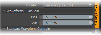
Bias: Affects the attenuation (the gradations) between the primary and secondary colors in a colored texture or the gray values in a grayscale texture. By increasing this value Modo favors the primary color (or value) over the secondary one. By decreasing the value Modo favors the secondary color (or value).

Bias 0% |
Bias 25% |
Bias 50% |
Bias 75% |
Bias 100% |
Gain: Affects the falloff of the gradient ramp between the primary color (or value) and the secondary color (or value). This is similar to a contrast control. Setting the Gain to 100% creates a very sharp contrast. Setting the value to 0% reduces the contrast between the two to an almost imperceptible amount.
Gain 0% |
Gain 25% |
Gain 50% |
Gain 75% |
Gain 100% |
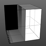
Waveforms - Fresnel
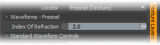
Index of Refraction: Attenuates the Fresnel falloff rate based on this value. The Fresnel (pronounced Fruh-nell) effect describes refractive and reflective properties of a surface when the viewer's angle relative to the surface changes. The rate at which the change happens is expressed in the Fresnel function. When applied to a gradient (such as one applied to the incidence angle of a surface), the Fresnel function produces the appropriate falloff rate.
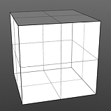
IOR 1.0 |
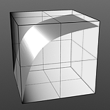
IOR 2.0 |
IOR 3.0 |
IOR 4.0 |
IOR 5.0 |
Waveforms - Gamma
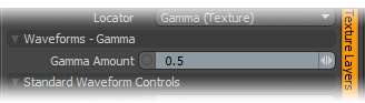
Gamma Amount: Manipulates the values across a spectrum. Like the Fresnel Index of Refraction option, Gamma is a nonlinear adjustment function for manipulating the values across a spectrum with the curve is expressed as a mathematical function. When applied to a texture layer, adjustments to the mid-tone value (those between black and white favoring the darker side) match any gamma adjustment values applied to image map layers directly. A value of 1 produces no results because the output matches that of the input. Values less than 1 darken the gradient; values greater than 1 lighten it.
Gamma 0.5 |
Gamma 1.0 |
Gamma 1.5 |
Gamma 2.0 |
Gamma 3.0 |
Waveforms - Gaussian
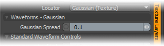
Gaussian Spread: Adjusts the values of a graduated texture layer based on a Gaussian distribution. A Gaussian distribution is a mathematical function that determines the spread of a number of values across a spectrum.
Spread 0.1 |
Spread 0.3 |
Spread 0.5 |
Spread 0.75 |
Spread 1.0 |
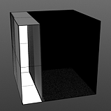
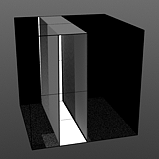
Waveforms - Impulse
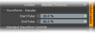
Start Pulse: Clamps the values of the gradient at the user-defined Start position and maximizes all values in between based on both the Start Pulse and End Pulse values.
End Pulse: Clamps the values of the gradient at the user-defined End position and maximizes all values in between based on both the Start Pulse and End Pulse values.
Start 0/End 25 |
Start 25/End 50 |
Start 25/End 75 |
Start 50/End 75 |
Start 75/End 100 |
Waveforms - Noise
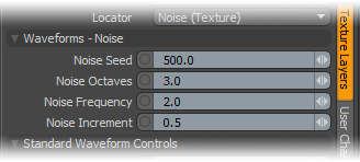
Noise Seed: Specifies the initial number Modo uses when generating values. Different Seed values produce dramatically or subtly different results. Use the same Seed value when you want items to retain the same variations.
Noise Octaves: Determines the number of layers of noise that Modo combines to produce the final result. Higher values produce more randomized (and detailed) results.
Octaves 1 |
Octaves 2 |
Octaves 3 |
Octaves 4 |
Octaves 5 |
Noise Frequency: Determines the number of occurrences of the noise function when applied to the surface.
Frequency 1 |

Frequency 2 |
Frequency 3 |
Frequency 4 |
Frequency 5 |
Noise Increment: Determines the number of noise bands across each Frequency occurrence.
Increment 0.0 |
Increment 0.25 |

Increment 0.5 |
Increment 0.75 |
Increment 1.0 |
Waveforms - Ramp
Ramp has no user-controlled settings.

Waveforms - Rounded
Rounded has no user-controlled settings.
Waveforms - S-Curve
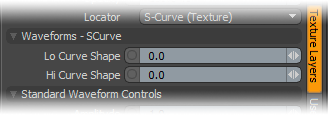
Lo Curve Shape: Determines the low-cutoff area for the gradient that the S-Curve waveform function produces.

Lo Curve 0 |
Lo Curve 1 |
Lo Curve 2 |
Lo Curve 3 |
Lo Curve 4 |
Hi Curve Shape: Determines the high-cutoff area for the gradient that the S-Curve waveform function produces.
|
Hi Curve 0 |
Hi Curve 1 |
Hi Curve 2 |
Hi Curve 3 |
Hi Curve 4 |
Waveforms - Sawtooth
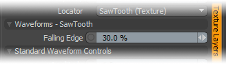
Falling Edge: Determines the position for the sudden minimum value drop in the graduated spectrum.
|
Falling Edge 0 |
Falling Edge 25 |
Falling Edge 50 |
Falling Edge 75 |
Falling Edge 100 |
Waveforms - Scallop
Scallop has no user-controlled settings.
Waveforms - Sine
Sine has no user-controlled settings.

Waveforms - Smooth
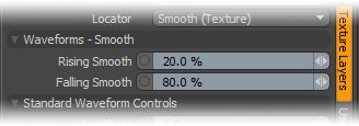
Rising Smooth: Specifies the minimum value for the a smooth S-shaped curve. The Smooth waveform produces a result similar to the Impulse waveform by maximizing values between a low and high end, but between the minimum value and the maximum value it produces a smooth S-shaped curve.
Falling Smooth: Specifies the maximum value for the a smooth S-shaped curve. The Smooth waveform produces a result similar to the Impulse waveform by maximizing values between a low and high end, but between the minimum value and the maximum value it produces a smooth S-shaped curve.
Rise 0/Fall 25 |
Rise 25/Fall 50 |
Rise 25/Fall 75 |
Rise 50/Fall 75 |
Rise 75/Fall 100 |
Waveforms - Smooth Impulse
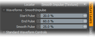
Start Pulse: Specifies the beginning of the maximal part of the Smooth Impulse waveform, which is a cross between the Impulse waveform and the Smooth waveform. The Start Pulse option reveals the Impulse waveform aspect of this combined waveform.
End Pulse: Specifies the end of the maximal part of the Smooth Impulse function, which is a cross between the Impulse function and the Smooth function. The End Pulse option reveals the Impulse waveform aspect of this combined waveform.
|
Start 0/End 25 |
Start 25/End 50 |
Start 25/End 75 |
Start 50/End 75 |
Start 75/End 100 |
Smooth Pulse: Determines the amount of smoothing applied to the Smooth Impulse waveform. The Smooth Pulse option reveals the Smooth waveform aspect of this combined waveform.

Smooth 0% |
Smooth 25% |
Smooth 50% |
Smooth 75% |
Smooth 100% |
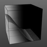
Waveforms - Smooth Step
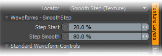
Step Start: Determines the start position for the smoothed step ramp.
Start 0% |
Start 25% |
Start 50% |
Start 75% |
Start 100% |
Step Smooth: Determines the amount of smoothing applied to the step position.
Smooth 0% |
Smooth 25% |
Smooth 50% |
Smooth 75% |

Smooth 100% |
Waveforms - Staircase
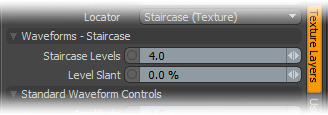
Staircase Levels: Determines number of discreet levels that the Staircase waveform breaks the smooth gradations into to produce a posterized effect.
Levels 1 |
Levels 2 |
Levels 4 |

Levels 8 |

Levels 16 |
Level Slant: Interpolates between the step levels to produce a less abrupt change from one step level to the next.
|
Slant 0% |
Slant 25% |
Slant 50% |
Slant 75% |
Slant 100% |
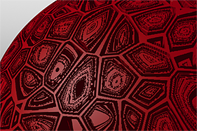
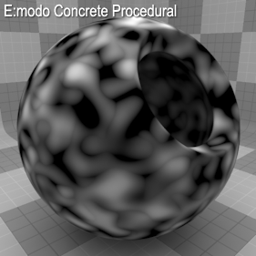
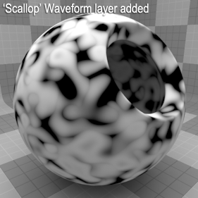
This gallery of rendered images illustrates the Waveform functionality.
|
|
|
|
|
|
|
|
|
|
|
|
|
|
|
|
|
|
|
|
|
|
|
|
|
|
|
|
|
|
|
|