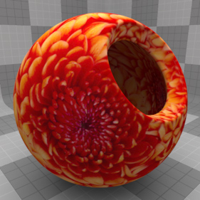
The image map item could be considered the most important texture layer as it allows you to apply bitmap images to surfaces in Modo. When originating from a photographic source, bitmaps are a means of literally getting the richness of the real world into Modo, producing effects that would be difficult, if not impossible to produce otherwise. Want a surface to look like asphalt or dirt? Take a photograph and apply it as an image map; photographic textures are essential to photo-real rendering.
Images created in editing/painting and illustration/typographic programs are extremely useful as well; labels, posters, and other signage are great examples of this application. Image maps shouldn't be strictly limited to representing textured surfaces either, as they are also useful in many other cases; they can represent multiple complex procedural layers baked together, reducing the calculation overhead. They can be displacement maps created by Modo or other packages that apply high frequency details to lower resolution subdivision surface models, providing a better level of interactivity to items among other benefits.
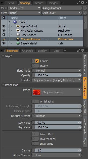
You can add an image map in the menu bar, by clicking Texture > Add Shader Tree Layer > Image Map or using the Add Layer function at the top of the full Shader Tree. The image map item contains all the attributes directly related to Modo's usage of the bitmap and are available in the Properties viewport when the item layer is selected in the Shader Tree. Scale, Position, Projection and other mapping-specific settings are available in the associated Texture Locator.
|
Option |
Description |
|---|---|
|
Layer |
|
|
Enable |
Toggles the effect of the layer on and off to duplicate the functionality of toggling visibility in the Shader Tree. When disabled, the layer has no effect on the shading of the scene. However, Modo saves disabled layers with the scene, and they are persistent across Modo sessions. |
|
Invert |
Inverts the colors (RGB values) for the layer to produce a photonegative effect. |
|
Blend Mode |
Affects the blending between different layers of the same effect type. With this, you can stack several layers for different effects. For more about blending, see the Layer Blend Modes topic. |
|
Opacity |
Changes the transparency of the current layer. Reducing this value increasingly reveals lower layers in the Shader Tree, if present, or dims the effect of the layer, itself, on the surface. |
|
Locator |
Most texture layers also have an associated Texture Locator that is automatically created in the Items list. This defines the mapping of the texture to the surface. The Locator option sets that association. You can choose alternate locators, however, the need to do so is very rare; still, there are some possible instances where you may want multiple texture items to share a single locator. |
|
Image Map |
|
|
Image |
This pop-up allows you to select or load the specific image to be applied. Additionally, there are options for creating new blank images which can be useful for painting, sculpting and image baking. |
|
Antialiasing |
This checkbox toggles the Antialiasing function for the selected image layer, a means of filtering the texture to produce smoother rendered results. Antialiasing samples the image's pixels in texture space (as opposed to screen or render space) and averages them based on spot size and strength. When enabled, the Antialiasing Strength and Minimum Spot options become available. |
|
Antialiasing Strength |
Active only when Antialiasing is enabled, this setting allows you to control the amount of antialiasing on the image. Setting this value above 100% creates a blurring effect that smoothes the texture image. |
|
Minimum Spot |
The spot size relates to the spot created on the surface of a mesh when intersected by a ray. Rays are actually conical; think of the beam of light from a flashlight. The further the ray's origin is from the surface that it intersects the larger the spot is. Further, if the ray hits the surface at an glancing angle it can be even larger. When there is an image applied to the surface in question the render engine needs to know how many 2D texture pixels should be sampled within that spot. This becomes more important the closer the camera is to the surface. If the minimum spot value is 1 or smaller the spot size is not clamped and accurately samples the texture image at the sub pixel level, if necessary. When the spot size is set to a value of 2 or higher, the number of pixels sampled is always greater than 1. This results in a slight blurring of the image. You rarely need to adjust this value. The default of 1 means that the spot size is accurate to the sub-pixel level. Increasing the minimum spot size is mostly useful for blurring an image or reducing details when using an image for an environment map. |
|
Texture Filtering |
When spot size is set to 1 and the camera is so close to a surface that it samples the image at the sub-pixel level (that is, an image pixel is bigger than a rendered pixel), Texture filtering averages across those samples. The result is a smooth interpolation of pixels rather than sharp angular pixel boundaries. You can choose from several options. • Nearest: Disables filtering of image, the actual pixel of the image is sampled. • Bilinear: Samples neighboring pixels vertically and horizontally, producing smooth, or slightly blurry results. • Bicubic: Samples all adjacent pixels providing the smoothest result. |
|
Low/High Value |
These values provide a means to re-map the total range of tones in an image, especially useful for controlling value setting. For instance, if you are using an image as a displacement map, you might want the darkest pixels to push the surface in and the bright pixels to push them out. By default, the pixels of an image go from 0 to 100% which means that none of the pixels yield a value to push the pixels inward. By setting the value range from -100% to 100%, the image is effectively remapped, so that the black pixels create a negative displacement and the white pixels a positive displacement with mid-tones being neutral. These settings are also useful in extending the range of standard (low dynamic range) images, making it possible to use standard non-HDR images to light a scene (although the results don't look as good as using a real HDRI). • Low Value- Determines the effective value of pixels that have a true value of 0,0,0 (r,g,b) • High Value- Determines the effective value of pixels that have a true value of 255,255,255 (r,g,b). |
|
Invert Red, Green, Blue |
These three checkboxes allow you to invert any of the three color channels of an image map individually. While you rarely need to use this option, especially on color images, it can be helpful to save normal maps where certain channels are mapped differently to what Modo expects them to be. |
|
Gamma |
This can be used as an image adjustment control to lighten or darken the image without the need to externally adjust it in an external bitmap editor. The Gamma adjustment is non-linear and affects the mid-tones of the image greater than the shadow and highlight areas of the image. For best results, leave the Gamma value at the default 1.0. |
|
Alpha Channel |
Allows you to choose how Modo handles alpha channel data (if present) contained in the image file. Use Alpha: Masks the color pixels based on the embedded alpha channel data. |
UV
|
Option |
Description |
|---|---|
|
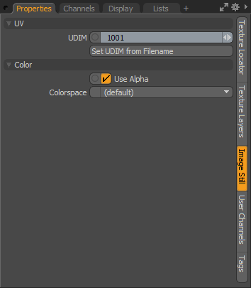
UDIM |
The UDIM value is a notation that designates an offset to a specific UV tile location. It is designed to allow you to assign many textures to a surface at once. For more information on using and working with UDIM textures, see the UDIM Workflow topic. |
|
Set UDIM from Filename |
Clicking this button causes Modo to read the filename for the selected texture layer(s) and automatically set the above UDIM value based on the filename. |
|
Color |
|
|
Use Alpha |
In certain game asset workflows, an embedded alpha channel on an image map might represent an effect other than the image's transparency. When set as such, it makes it difficult to view the image in the 3D Viewports. In these cases the Use Alpha option is a global way to disable any embedded alpha channels from an image, allowing its color components to still be visible. |
|
Colorspace |
This setting defines the color space of the associated image layer, which controls how Modo interprets the colors of the image itself for rendering. The settings for the Colorspace option can have a dramatic effect over how the colors look in the final rendered image, so setting it properly is important. For more information on a color managed worflow in Modo, see the Color Management topic. |
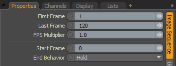
Additional options appear when you apply an image sequence as a texture layer. To access these options, select the image sequence item, then select the Image Sequence sub-tab from the Shader Tree Properties panel.
|
Option |
Description |
|---|---|
|
First/Last Frame |
These options determine the range from the sequence to display/render in Modo. Frames outside of this range are ignored/truncated. |
|
FPS Multiplier |
This value determines the speed at which the sequence plays in relation to the FPS rendered in the Modo scene, allowing you to adjust the timing of frames. So a 30fps image sequence applied to a 30fps plays at 1:1 frames when the value is 1.0 (one sequence frame for every rendered frame). A 2.0 value is twice as fast as the scene, effectively skipping every other frame, conversely a 0.5 value plays back half as fast, doubling the frames. NOTE: This speed affects the Start Frame value below. A Start Frame of 48 starts at 24 when the speed is 2.0. |
|
Start Frame |
This value determines the first rendered frame in Modo in which to begin the playback of the image sequence, allowing you to delay the start of the sequence. Frames rendered prior to this value hold the First Frame as specified above, duplicating the First Frame in subsequent rendered frames until reaching the Start Frame value. |
|
End Behavior |
These options determine how Modo handles the image sequence when the Last Frame value is reached. Hold: Duplicates the Last Frame on all subsequent rendered frames. Repeat: Loops the sequence between the First and Last Frame values. Mirror: Ping-pongs the sequence forwards and backwards between the First and Last Frame values. |
TIP: Modo automatically uses the first available or last available frame when corresponding frames don't exist in the specified sequence. Take, for example, a sequence from frame 45 to 100 applied as a background plate. If the First and Last Frame values are 1 and 100 respectively, and the Start Frame value is 0, when rendering out the sequence, frame 45 would be duplicated across rendered frames 1-44 as no frames existed in the specified sequence - essentially the same behavior as the First /Last option. Interim missing frames are duplicated until a proper sequence frame is encountered.