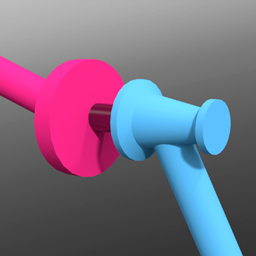
The pin constraint type is a rigid constraint meant to rigidly attach two or more dynamic items together. This can be useful for attaching together two object with dramatically different mass values, such as the metal head of a hammer attached to its wooden handle. The heavier head affects the whole hammer. It is also useful to rigidly combine shattered objects that are meant to break apart when combined with the Stress Break function.
To apply a pin constraint automatically, follow these steps:
| 1. | Select two items prior to invoking any of the constraint types. |
The first item selected represents the master or parent item and is defined as Body A in the constraint, the second item selected is the item that is constrained, also considered the auxiliary or child item, defined as Body B.
| 2. | With the items selected, in the Dynamics sub-tab, click on the Pin constraint button. |
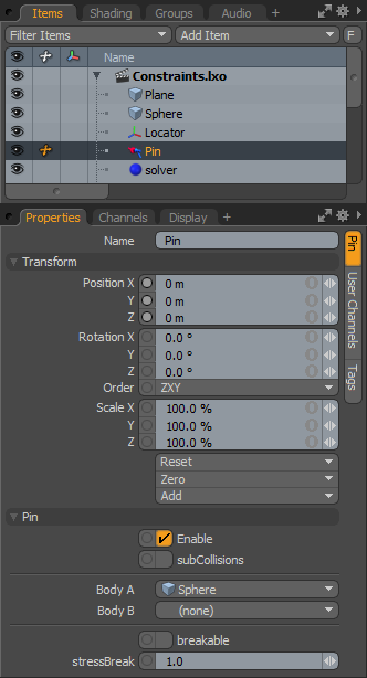
This adds the constraint item to the Items list.
The default center location of the pin constraint is exactly halfway between the Body A and Body B objects with a line drawing to the centers of the constrained items.
|
Option |
Description |
|---|---|
|
Name |
Displays the current constraint item name. To change it, click on the field and type in the new name. |
|
Transform |
|
|
Position X/Y/Z |
These values represent the initial center for the constraint item in 3D world space, and the center of mass relative to the item it is constraining. Based on its initial position, once a dynamics simulation is invoked, the constraining item rotates and moves based on its initial (resting) position. |
|
Rotation X/Y/Z |
These values represent the initial (resting) rotation of the constraining item. |
|
Scale X/Y/Z |
These values have no direct effect on constraints. |
|
Pin |
|
|
Enable |
Toggles the constraint item on or off. When enabled, the constraint item is considered during a dynamics simulation; when disabled, the constraint item is ignored. However, disabled constraints are persistent across Modo sessions, being saved with the scene, and retain their present settings. |
|
SubCollisions |
When enabled, allows constrained objects (especially those within a chain, not a literal chain, but subsequent groupings) to collide with one another. When disabled (the default state), fewer calculations are required, however, constrained items may inter-penetrate each other. If this occurs, enable SubCollisions. |
|
Body A |
Represents the item that another item is constrained to, the parent or master item. |
|
Body B |
Represents the item that is constrained, the child or auxiliary item. |
|
Breakable |
Allows constraints to be broken apart when a certain stress threshold is reached, defined by the Break Stress value. When the threshold is reached, the constraint no longer has any effect on the constrained item, leaving it to be affected by any other forces present in the simulation. |
|
Stress Break |
Determines the threshold when the constraint no longer affects the constrained item. The Breakable option must be enabled for this value to have any effect on the constraint. |