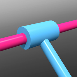
The slide hinge constraint combines the dynamic actions of the hinge with a slide constraint, providing the rotation movement of the hinge with the addition of a linear back-and-forth sliding motion.
To apply a slide hinge constraint automatically, follow these steps:
| 1. | Select two items prior to invoking any of the constraint types. |
The first item selected represents the master or parent item and is defined as Body A in the constraint, the second item selected is the item that is constrained, also considered the auxiliary or child item, defined as Body B.
| 2. | With the items selected, in the Dynamics sub-tab, click on the Slide Hinge constraint button. |
This adds the constraint item to the Items list.
The default center location of the slide hinge constraint is exactly halfway between the Body A and Body B objects with a line drawing to the centers of the constrained items. Depending on your intentions, this might not be the optimal position for the constraint. The motion of the child item (Body B) originates from the position of the constraint item itself, so it may need to be positioned appropriately.
|
Option |
Description |
|---|---|
|
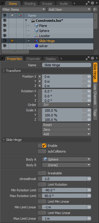
Name |
Displays the current constraint item name. To change it, click on the field and type in the new name. |
|
Transform |
|
|
Position X/Y/Z |
These values represent the initial center for the constraint item in 3D world space, and the center of mass relative to the item it is constraining. Based on its initial position, once a dynamics simulation is invoked, the constraining item rotates and moves based on its initial (resting) position. |
|
Rotation X/Y/Z |
These values represent the initial (resting) rotation of the constraining item. |
|
Scale X/Y/Z |
These values have no direct effect on constraints. |
|
Slide Hinge |
|
|
Enable |
Toggles the constraint item on or off. When enabled, the constraint item is considered during a dynamics simulation; when disabled, the constraint item is ignored. However, disabled constraints are persistent across Modo sessions, being saved with the scene, and retain their present settings. |
|
SubCollisions |
When enabled, allows constrained objects (especially those within a chain, not a literal chain, but subsequent groupings) to collide with one another. When disabled (the default state), fewer calculations are required, however, constrained items may inter-penetrate each other. If this occurs, enable SubCollisions. |
|
Body A |
Represents the item that another item is constrained to, the parent or master item. |
|
Body B |
Represents the item that is constrained, the child or auxiliary item. |
|
Breakable |
Allows constraints to be broken apart when a certain stress threshold is reached, defined by the Break Stress value. When the threshold is reached, the constraint no longer has any effect on the constrained item, leaving it to be affected by any other forces present in the simulation. |
|
Stress Break |
Determines the threshold when the constraint no longer affects the constrained item. The Breakable option must be enabled for this value to have any effect on the constraint. |
|
Limit Rotation |
The hinge part of this constraint is not initially limited in its rotation. By enabling this option, you can constrain the range of rotation that can be applied to the constraint, similar to the motion of a door hinge that is allowed to only swing so far. |
|
Min/Max Rotation Limit |
The Minimum value sets the lower extreme of the of the rotation clamping, while the Maximum value limits the upper extreme value. |
|
Limit Min/Max Linear |
By default, the motion of the constrained item is not limited across the length of the constraining line. Enabling the upper and/or lower limits allows you to restrict the motion to a specific range, determined by the Min/Max position values. |
|
Min/Max Limit Linear |
When the Limit Min/Max Linear values are enabled, you can define a range as a distance value offset from the constraint's center position. |