The Box primitive provides a simple method for creating boxes or cubes. There are many parameters available to create variations on the default 1-meter cube. By dragging in the 3D Viewport with the Box tool active, you can create the initial plane for the box. Once the initial plane is created, clicking away from one of the handles snaps that handle to the mouse position so that you can add dimension to the shape, or simply change the current values.
There are also alternate commands assigned to all of the primitive tool icons. The alternate commands allow you to Ctrl+click on the icon to quickly create a unit primitive without interacting with the tool, or allow you to Shift+click the icon to create a unit primitive inside a new Mesh Item layer.
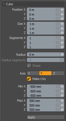
The following Cube options are available for editing the primitive created:
|
Cube |
|
|---|---|
|
Center X, Y, Z |
These three values establish the 3D location for the center of the cube. |
|
Size X, Y, Z |
These three values are used to establish the dimensions of the cube. Set to 1 m, 1 m, 1 m (by default), this option provides us with a 1-meter cube. If you want to create a 6-foot plank that is 2 inches by 4 inches, you can type into the X, Y, and Z numeric fields 6' 2" 4",respectively, and Modo performs the measurement translation to the current unit mode (Metric, SI, or English). |
|
Segments X, Y, Z |
By default, the primitive box uses a single segment on each axis. By increasing this value, you can increase the number of "cuts" in each side of the box. This is useful if you plan to deform the cube, as these segments act as hinges during deformation operations. |
|
Radius |
This distance value sets a curved edge amount. When radius is set to a positive non-zero value, the edge of the box is rounded off using extra segments, added to the geometry. The number of segments is determined by two additional settings: Radius Segments and Sharp. |
|
Radius Segments |
When the Radius value is set to a positive, non-zero value, additional segments are added to round the cube. The Radius Segments field allows you to set how many edges are added to smooth out the corners. |
|
Sharp |
This adds an extra set of polygons to the edge of the rounded edge so that the adjacent faces are not affected by surface smoothing. This allows the surface material to use smoothing to further round the edges without losing the flat appearance of the faces of the cube. |
|
Axis |
Defines the major axis for the cubes orientation. On the cube this only affects the direction of Radius Segments. |
|
Make UVs |
When this button is active a UV map is automatically generated for the geometry created with the tool. This is a very useful option if you plan to UV map the model you are creating from the primitive, as it provides a baseline UV map that you can massage later in the modeling process. In many cases, this can reduce the amount of work required to map the model. |
|
Min X, Y, Z/Max X, Y, Z |
You can also define a cube, based on specific X, Y, and Z bounding box locations in 3D space, which can be specified here. This makes it easy to place a cube on the ground plane for instance by making the Min Y value 0 and the Max Y value 1m. |
TIP: The Box primitive supports symmetrical creation. When Symmetry is activated, creating the primitive shape creates an identical version across the specified axis.