The Cylinder primitive provides a simple method for creating cylinders or tubes. There are many parameters available to create variations on the default 1-meter cylinder. By dragging in the 3D Viewport with the Cylinder tool active, you can create the initial end-cap for the cylinder. Once the initial cap is created, clicking away from one of the handles snaps that handle to the mouse position so that you can add dimension to the shape, or simply change the current values.
There are also alternate commands assigned to all of the primitive tool icons. The alternate commands allow you to Ctrl+click on the icon to quickly create a unit primitive without interacting with the tool, or allow you to Shift+click the icon to create a unit primitive inside a new Mesh Item layer.
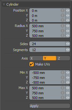
The following Cylinder options are available for editing the primitive created:
|
Cylinder |
|
|---|---|
|
Position X, Y, Z |
These three values establish the location for the center of the cylinder. |
|
Radius X, Y, Z |
These three values establish the dimensions of the cylinder, based on the radius. |
|
Sides |
This value determines how many edges are used to define the cylinder's circumference. The larger the number of sides, the smoother the cylinder appears. If you plan to use subdivision surfaces on the cylinder, use a low number. |
|
Segments |
By default, the primitive cylinder uses 12 segments. By increasing this value you can increase the number of "cuts" along the cylinder. This is useful if you plan to deform the cylinder, as these segments act as hinges during deformation operations. |
|
Axis |
This X, Y, Z choice allows you to quickly change the orientation of the primitive. |
|
Make UVs |
When this button is active, a UV map is automatically generated for the geometry created with the tool. This is a very useful option if you plan to UV map the model you are creating from the primitive, as it provides a baseline UV map that you can massage later in the modeling process. In many cases this can reduce the amount of work required to map the model. |
|
Min X, Y, Z/Max X, Y, Z |
you can also define a cylinder based on specific X, Y, and Z bounding box locations in 3D space, which can be specified here. This makes it easy to place the cylinder on the ground plane, for instance, by making the Min Y value 0 and the Max Y value 1m. |
TIP: The Cylinder primitive supports symmetrical creation. When Symmetry is activated, creating the primitive shape creates an identical version across the specified axis.