The Torus primitive provides a simple method for creating toroids or "doughnuts". There are several parameters available to create variations on the default torus. By dragging in the 3D Viewport with the tool active, you can create the initial plane for the primitive. Once the initial plane is created, clicking away from one of the handles snaps that handle to the mouse position so that you can add dimension to the shape, or simply change the current values. If you wish to drag out a 3D torus, hold the Ctrl key while dragging in the 3D view.
Thereare also alternate commands assigned to all of the primitive tool icons. The alternate commands allow you to Ctrl+click on the icon to quickly create a unit primitive without interacting with the tool, or allow you to Shift+click the icon to create a unit primitive inside a new Mesh Item.
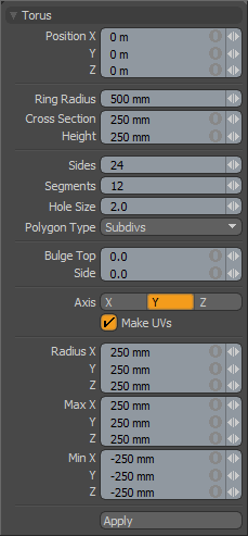
The following Torus options are available for editing the primitive created:
|
Torus |
|
|---|---|
|
Position X, Y, Z |
These three values establish the 3D location for the center of the primitive. |
|
Ring Radius |
Determines the overall outside width of the torus. |
|
Cross Section/Height |
A Cross Section width and Height setting, determining the sizing of the ring cross section of the torus. |
|
Radius X, Y, Z |
These three values establish the dimensions of the torus. The tool is set to 50cm, 50cm, 50cm by default. |
|
Sides |
The sides are the latitudinal edges of the torus running from top to bottom. By default, the primitive uses 24 sides. By increasing this value, you can increase the number of "cuts" in the shape. This is useful if you plan to deform the mesh, as these segments act as hinges during deformation operations. This also increases the smoothness of the capsule by adding extra facets. If you plan to apply subdivision surfaces to this shape, you can use a lower number of sides. |
|
Segments |
The segments are the longitudinal edges of the torus running from right to left. By default, the primitive uses 12 segments. By increasing this value, you can increase the number of "cuts" in the shape. This is useful if you plan to deform the shape, as these segments act as hinges during deformation operations. It also increases the smoothness of the shape by adding extra facets. If you plan to apply subdivision surfaces to this shape, you can use a lower number of segments. |
|
Hole Size |
This value sets the radius of the hole in the middle of the torus. |
|
Polygon Type |
You can use this option to determine the type of polygons created: • Face - creates standard, unsmoothed polygon faces. • Subdivs - creates Subdivision Surface smoothed polygons. • Catmull-Clark - creates Pixar Catmull-Clark smoothed polygons. |
|
Bulge Top/Side |
Raising this value above zero (0) attenuates the shape towards a more cubic or box-like form. |
|
Axis |
This X, Y, Z choice allows you to quickly change the orientation of the primitive. |
|
Make UVs |
When this button is active, a UV map is automatically generated for the geometry created with the tool. This is a very useful option if you plan to UV map the model you are creating from the primitive, as it provides a baseline UV map that you can massage later in the modeling process. In many cases, this can reduce the amount of work required to map the model. |
|
Radius |
Determines the size from the center of the Torus to the outer bounding box edge - the radius - of the torus. |
|
Min XYZ/Max XYZ |
You can also define the shape based on specific X, Y, and Z bounding box locations in 3D space, which can be specified here. This makes it easy to place the torus on the ground plane, for instance, by making the Min Y value 0 and the Max Y value 1m. |
TIP: The Torus primitive supports symmetrical creation. When Symmetry is activated, creating the primitive shape creates an identical version across the specified axis.