In Modo, the effect any tool has upon a selected region of geometry is rigid, meaning applications of a tool happen at a constant rate across the selected range. Modo provides a way to attenuate the effect a tool has over a selection as a falloff, a gradual decrease in intensity across a defined range. falloffs are universal in application, once activated, they are persistent until disabled, and work with all the various tools. In fact, many tools are simply pre-made combinations of a specific falloff and a transform. For example, if you add the Rotate tool to a Linear falloff , you get a Twist tool. This is made possible using the power of the Tool Pipe.
You can define a falloff in multiple ways.
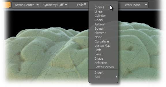
| 1. | Select one in the Falloff dropdown menu in the interface, in the Falloff selector menu, or in the menu bar under Edit > Falloff. |
The selected falloff has a checkmark next to its name to indicate its active state.
| 2. | Once you've selected a falloff, click and drag in the viewport to define the range. |
Taking its position cue from the Work Plane, the first click defines the origin or center of the falloff, and the drag action defines the size or range.
| 3. | Release the mouse button to accept the falloff. |
Any subsequent tool applications utilize the falloff until it is disabled by selecting (none) or pressing Esc.
When a falloff of is active, its properties are visible within the tools properties panel, as an adjunct to the tool's properties. Each has its on specific settings. Anytime a tool is in interactive mode, you can modify the input values and receive real-time feedback of the results. Additionally, you can adjust the tool directly in the viewport by clicking and dragging the widgets visible on the Falloff display.
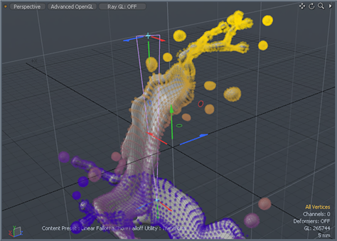
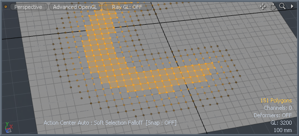
If a tool is active when setting a falloff, such as the Move or Rotate tools, the act of simply selecting the falloff type in the menu automatically scales the falloff to the bounding box size of the active selection (if nothing is selected, all geometry is affected). This functionality makes it easy to accurately apply falloffs when modeling. To better visualize the effect a falloff has over a selection, enable the Show Falloffs option in the menu bar under View > Show Falloffs. This colorizes the vertices depending on the amount of influence a falloff has over them, dark purple for no influence, transitioning toward yellow for full influence as demonstrated by the image below (with a Linear falloff on the Y axis).
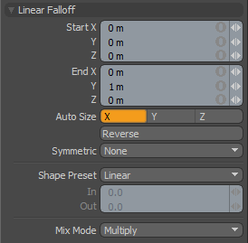
Linear falloff uses a straight line to define the falloff. The line itself determines the direction of the falloff's influence with the strength of the effect itself, reaching out toward infinity. All the vertices at one end of the line receive 100% of the tool's influence. The vertices at the other side receive 0% of the tool's influence. The points between the two lines receive some partial value based on the interpolation between the two end points.
Start X/Y/Z: Defines the starting position of the falloff as a specific XYZ coordinate value. This end of the line and everything beyond it receives the maximum amount of influence attenuating toward the 'End' position.
End X/Y/Z: Defines the end position of the falloff as a specific XYZ coordinate value. This end of the line and everything beyond it receives no influence attenuating toward the Start position.
Auto Size X/Y/Z: You can select either of these three options to automatically scale the Start and End points of the falloff to match the bounding box size of the selected elements along one of the three axes.
Reverse: You can select this option to invert the Start and End points reversing the influence of the falloff.
Symmetric: You can choose from several options to automatically mirror the influence area of the falloff:
• None: The Symmetric function is disabled.
• Start: Influence of falloff is symmetrically mirrored across the Start position.
• End: Influence of falloff is symmetrically mirrored across the End position.
Shape Preset: The strength of the falloff's influence can be controlled along the extent using a shape preset.
Linear: Attenuation of falloff occurs evenly across its range.
• Ease-In: Strength of falloff is greater toward the Start position.
• Ease-Out: Strength of falloff is greater toward the End position.
• Smooth: Strength of falloff is greater toward the center of the falloff.
• Custom: You can use the In/Out options to fine-tune the strength of the falloff.
In/Out: The In value determines the strength of the falloff nearer to the Start position and the Out value determines the strength on nearer the End side of the falloff.
Mix Mode: In instances where there are multiple falloffs applied to a transform (using the Add option of the Falloff menu), the mix mode defines how each falloff interacts with the other.
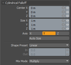
The Cylindrical falloff creates a circular falloff that extends across the length of a virtual cylinder. All vertices at the center of the cylinder receive 100% of the tool's influence, attenuated toward the outer edge and beyond the cylinder, where vertices receive none of the tool's influence.
Center X/Y/Z: Defines the center of influence, where the strength of the falloff is greatest (100%). The strength of the falloff attenuates toward the outer bounds of the cylinder. The falloff volume extends upward and downward toward infinity.
Size X/Y/Z: Defines the radius of a perfect circle from the center and determines the outer area of the falloff where there is no effect.
Axis: Defines the projection axis for the cylinder, determining the direction for the falloff.
Auto Size: You can select this option to automatically size the falloff's Center and Size values to match the bounding box of the current selection.
Shape Preset: The strength of the falloff's influence can be controlled along the extent using a shape preset.
• Linear: Attenuation of falloff occurs evenly across its range.
• Ease-In: Strength of falloff is greater toward the Start position.
• Ease-Out: Strength of falloff is greater toward the End position.
• Smooth: Strength of falloff is greater toward the center of the falloff.
• Custom: You can use the In/Out options to fine-tune strength of falloff.
In/Out: The In value determines the strength of the falloff nearer to the Start position, and the Out value determines the strength on nearer the End side of the falloff.
Mix Mode: In instances where there are multiple falloffs applied to a transform (by using the Add option of the Falloff menu), the mix mode defines how each falloff interacts with the other.
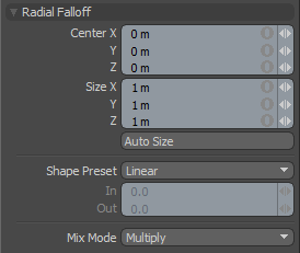
Radial falloff uses a sphere where all vertices at the very center of the sphere receive 100% tool influence and any vertices outside the sphere receive 0% of the tool's influence. There is a smooth gradient of tool influence between the center and edge boundary of the sphere that utilizes the falloff shape preset to determine the interpolation style.
Center X/Y/Z: Defines the center of influence, where the strength of the falloff is the greatest (100%). The strength of the falloff attenuates toward the outer bounds of the spherical volume, the area outside the volume receives no tool influence.
Size X/Y/Z: Defines the radius of a perfect circle from the center and determines the outer area of the falloff where there is no effect.
Auto Size: You can select this option to automatically size the falloff's Center and Size values to match the bounding box of the current selection.
Shape Preset: The strength of the falloff's influence can be controlled along the extent using a shape preset.
• Linear: Attenuation of falloff occurs evenly across its range.
• Ease-In: Strength of falloff is greater toward the Start position.
• Ease-Out: Strength of falloff is greater toward the End position.
• Smooth: Strength of falloff is greater toward the center of the Falloff.
• Custom: You can use the In/Out options to fine-tune strength of falloff.
In/Out: The In value determines the strength of the falloff nearer to the Start position, where the Out value determines the strength on nearer the End side of the falloff.
Mix Mode: In instances where there are multiple falloffs applied to a transform (by using the Add option of the Falloff menu), the mix mode defines how each falloff interacts with the other.
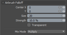
The Airbrush falloff allows a tool's influence to be painted onto a mesh. Unlike the other falloff tools, airbrush continually adds to the tool influence while you drag the brush around the mesh. This tool is similar to the Airbrush tool found in 2D paint programs, except rather than smoothly painting pixels into an image, the brush paints the tool influence into the mesh. This can be combined with many tools in Modo for a wide variety of effects. You can right-click and drag to interactively define the size of the brush applied.
To use the Airbrush falloff:
| 1. | Activate the falloff in Falloffs > Airbrush and apply the effect (such as Move). |
At first you can't see any results.
| 2. | Click and drag over the surface of the model to apply the tool's action to the geometry. |
You can set the following properties:
Center X/Y: Determines the current center position in the viewport of the brush tip. You can interactively click and drag over a model's surface to actually apply the falloff.
Size: Sets the pixel size of the Airbrush tip's influence, calculated as a radius from the Center position.
Strength: Defines the intensity of the falloff's application when brushing over a surface.
Transparent: When disabled, the falloff only affects polygons facing toward the viewport. When enabled, the falloff works through surface also affecting those facing away from the viewports.
Mix Mode: In instances where there are multiple falloffs applied to a transform (by using the Add option of the Falloff menu), the mix mode defines how each falloff interacts with the other.
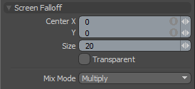
The Screen falloff is similar to the Cylinder falloff, except rather than using one of the major axes to determine the angle of the projection, the Screen falloff projects a cylinder that is perpendicular to the viewport window (the computer's screen). The falloff is defined by a disc drawn in screen space extending infinitely into the distance. This disc is used to project a virtual cylinder of influence.
Center X/Y: Defines the center of influence in screen space, where the strength of the falloff is greatest (100%). The strength of the falloff attenuates toward the outer bounds of the spherical volume, the area outside the volume receives no tool influence.
Size: Sets the pixel size of the circular area of influence, calculated as a radius from the Center position.
Transparent: When disabled, the falloff only affects polygons facing toward the viewport. When enabled the falloff works through surface also affecting those facing away from the viewports.
Mix Mode: In instances where there are multiple falloffs applied to a transform (by using the Add option of the Falloff menu), the mix mode defines how each Falloff interacts with the other.
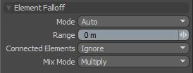
Element falloff limits the tool influence to the element (vertex, edge or polygon) in the mesh that is clicked on when using the current tool. You can hover the mouse pointer over a component (vertex, edge or polygon) and see the target element pre-highlighted. Clicking on the element applies the tool's action to the element, attenuating outward based on the Range value.
Mode: There are several modes available for selecting the element type.
• Auto: You can choose from any component, based on which element is clicked.
• Auto Center: Same as Auto, but the Range is calculated from the element's center point.
• Vertex: You are limited to only selecting vertices.
• Edge: You are limited to only selecting edges.
• Edge Center: Same as Edge, but the Range is calculated from the element's center point.
• Polygon: You are limited to only selecting polygons.
• Polygon Center: Same as Polygon, but the Range is calculated from the elements center point.
Range: This value determines the extent of the falloff range, measured outward from the tool handle. When the Center options are selected, the Range is calculated from the element's center point. At the default 0 m value, only the clicked element is affected.
Connected Elements: Defines what connected geometry does when an element is transformed.
• Ignore: Ignores all connected elements and only moves the element specified.
• Use Connectivity: Only affects single surface and connected elements. Unconnected elements within range are ignored.
• Rigid Connections: Moves all connected elements equally the specified distance.
• Edge Loops: Moves the connected loop, defined by all the connected quad polygons/edges/vertices in a single row.
Mix Mode: In instances where there are multiple falloffs applied to a transform (by using the Add option of the Falloff menu), the mix mode defines how each falloff interacts with the other.
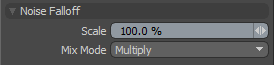
The Noise falloff uses a three-dimensional noise pattern to modulate the influence of the tool. You can adjust the size of the noise pattern with the scale parameter. Combined with the Move or Stretch tool, this falloff can be useful for roughing up a surface.
Scale: This value determines the size of the noise in relation to the geometry it is affecting.
Mix Mode: In instances where there are multiple falloffs applied to a transform (by using the Add option of the Falloff menu), the mix mode defines how each falloff interacts with the other.
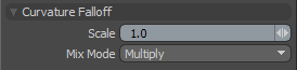
The Curvature falloff is defined by surface variation. Computing the same type of effect as the RT Curvature, the Curvature falloff is used to generate a falloff that attenuates across changes in surface topology, especially noticeable in areas of abrupt change or protrusion (producing an effect sometimes called an accumulation or dirt shader). Adjust the Scale value to apply the effect to concave or convex areas of the surface.
NOTE: The curvature is sampled based on continuous surfaces, intersecting surfaces are calculated independently. Also, surfaces with little topological variation (smooth surfaces) likely appear to produce little to no results.
Scale: This value determines the attenuation amount from one area to the next across topological changes. Reducing the scale tends to bias the effect toward concave areas, increasing it biases it outward from them. Setting the scale to negative values inverts the effect where the convex areas get masked by the falloff and the concave areas are affected.
Mix Mode: In instances where there are multiple falloffs applied to a transform (by using the Add option of the Falloff menu), the mix mode defines how each falloff interacts with the other.
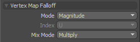
The Vertex Map falloff converts values of the currently selected Vertex Map to values representing falloff strength. While generally a Weight Map is used, being the most intuitive approach, you may also use values of other Vertex Map types as a falloff as well. The falloff is determined by the values of an existing Vertex Map. This allows you to create complex falloffs that actually can have a inverse negative in instances where negative values can be applied.
If a user chooses "Component" for the 'Mode' option, the falloff tool uses the component value specified by the index option. For example, if the current map is a Morph Map and the index is X, then the falloff sets the X value of morph position to the weight value. Magnitude is effective for morph, RGB, and RGBA maps. If the current map selected is a morph map, the falloff returns the length of the morph delta position. If it is RGB or RGBA, the falloff returns the luminosity of color vector.
Mode:
• Magnitude- Values of the Vertex Map are converted to strength values and applied to the affected surface(s).
• Component- You can select individual components of a map: Weight Map (1 component- weight value), RGB Map (3 components- R, G or B), RGBA Map (4 components- R, G, B or A), Morph Map (3 components- X, Y or Z), Pick Map (1 component)
Index: When Component mode is selected, you can determine the specific component using this option selector.
Mix Mode: In instances where there are multiple falloffs applied to a transform (using the Add option of the Falloff menu), the mix mode defines how each falloff interacts with the other.
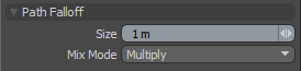
The Path falloff combines the curve generator with the Path falloff. The curve generator creates a curve and the falloff reads the curve points to determine where the tool should be active. If the user has the Path falloff in the Tool Pipe at the same time as a mesh edit or Transform Tool, they may need to select the Curve Path (in Polygons mode) prior to activating the falloff. This allows you to define the curve to be used. Once the basic curve is created, you can select the tool and begin to edit. You can also click on the curve control points to edit them while the tool/falloff combination is active.
Size: This value determines the area of attenuation around the path itself, calculated as a tube around the curve's position.
Mix Mode: In instances where there are multiple falloffs applied to a transform (by using the Add option of the Falloff menu), the mix mode defines how each falloff interacts with the other.
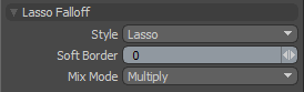
Several styles of Lasso selections drawn in screen space projecting outward toward infinity, producing very specific falloffs. Settings allow you to then to define areas of influence around the lasso shape with the 'Soft Border' option. All areas within the Lasso receive 100% of the tools effect; the attenuation of the falloff occurs across the 'Soft Border' distance only outside the Lasso area.
• Style: You can choose from the various Lasso styles.
• Lasso: Allows you to draw freeform shapes onto the screen defining the falloff.
• Rectangle: You can drag out rectangular shapes to define the falloff area.
• Circle: You can drag out perfectly circular shapes to define the falloff area. The shape originates from the center of the circle.
• Ellipse: You can drag out elliptical shapes to define the falloff area. The shape originates from the upper or lower corner of the ellipse.
Soft Border: This option defines the actual falloff radius around the Lasso area that attenuates across the distance defined. Calculated in screen-space pixels from the lasso border.
Mix Mode: In instances where there are multiple falloffs applied to a transform (using the Add option of the Falloff menu), the mix mode defines how each falloff interacts with the other.
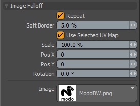
Similarly to the Image Ink option in the painting toolbox, you may apply an image, in screen space, as a falloff, where the brightness (luminosity) of the image affects the selected geometry. Additionally, by selecting the Use Current UV option of the falloff, you can apply the current image as a falloff in 3D object space opening up a whole variety of options.
To use, you need to place the masking image into the images folder of the presets, or add the path to the Preset Browser. Once the image is selected, clicking in the viewport activates the image widget, where you can use the controls to position the image within the 3D Viewport using the various handles.
Repeat: When this option is enabled, the image is repeated outside of the images borders. This has no effect when Use Selected UV Map is enabled.
Soft Border: Attenuates the strength of the image's effect over the geometry. At 100% the strength of the falloff is strongest at the center falling off toward the edges of the image. At 0%, the white areas of the entire image affect the geometry.
Use Selected UV Map: When this option is enabled, Modo bypasses the viewport image and applies the image's effect to the surface with the currently selected UV map. You can select UV maps within the List viewport under the UV Map section.
Scale: This value determines the size of the image in the 3D Viewport, and when Repeat is disabled, the size of the falloff's area of influence as well. Click the right side handle to interactively rotate the image.
Pos X/Y: Positions the center point of the Image within the 3D Viewport. You can also click the center handle on the widget to interactively position the image.
Rotation: Rotates the image within the 3D Viewport. Click the top handle to interactively rotate the image.
Image: Use this button to browse through the preset bitmap textures, selecting the image to use for the falloff.
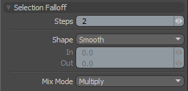
The Selection falloff allows you to modulate a geometry edit based on a selection area. The area of influence is at 0% on the selection border and ramps to 100% based on the Steps value. If the Steps are set to 1, there is only a slight falloff range, resulting in a harder edit. Increasing the number of Steps softens the influence at the selection border and the number of steps can be controlled by right-clicking or by editing the text field in the tool's Properties. You might think of Steps as rows or loops of selected elements: for each Step the falloff reduces the selection area and uses the range between the original selection and the reduced selection as the soft border for the falloff area.
Steps: This value determines the extent of the falloff range, where each Step represents a loop of polygons or a ring of edge sections. The greater the Steps value, the further the falloff attenuates.
Shape: The strength of the falloff's influence can be controlled along the extent using a shape preset.
• Linear: Attenuation of the falloff occurs evenly across its range.
• Ease-In: Strength of the falloff is greater toward the Start position.
• Ease-Out: Strength of falloff is greater toward the End position.
• Smooth: Strength of falloff is greater toward the center of the falloff.
• Custom: You can use the In/Out options to fine-tune the strength of the falloff.
In/Out: The In value determines the strength of the falloff nearer to the Start position, and the Out value determines its strength nearer the End side of the falloff.
Mix Mode: In instances where there are multiple falloffs applied to a transform (by using the Add option of the Falloff menu), the mix mode defines how each falloff interacts with the other.

The Soft Selection falloff is unique in that it is the only falloff that modulates the geometry outside of the selection.
Radius: Determines the range outside of the selected edge to attenuate the falloff.
Use Connectivity: When enabled, only affects single surface/connected elements. Unconnected elements within range are ignored.
Shape: The strength of the falloff's influence can be controlled along the extent using a shape preset.
• Linear: Attenuation of the falloff occurs evenly across its range.
• Ease-In: Strength of the falloff is greater toward the Start position.
• Ease-Out: Strength of falloff is greater toward the End position.
• Smooth: Strength of falloff is greater toward the center of the falloff.
• Custom: You can use the In/Out options to fine-tune the strength of the falloff.
In/Out: The In value determines the strength of the falloff nearer to the Start position, and the Out value determines its strength nearer the End side of the falloff.
Mix Mode: In instances where there are multiple falloffs applied to a transform (by using the Add option of the Falloff menu), the mix mode defines how each falloff interacts with the other.
Show Weights
Show Vertex/Show Edge: You can use these toggles to enable/disable the display of geometry highlights for both vertices and edges, giving a visual reference to the application of the Soft Selection falloff (demonstration of the vertices display mode below).
NOTE: Commands such as Copy, Paste or Delete are typically all or nothing type events and are therefore unaffected by falloffs.