Using a flat screen to create and edit content in 3D space can sometimes feel awkward and unnatural. Software has tried to resolve the disconnect using different solution over the years. The most popular is the four viewport method. Each orthogonal viewport only provides two axes at any given time, eliminating surprises as you create and modify geometry in a given scene. Another solution is working with tool handles constraining operations performed in a perspective viewport to the same flat 2D axes of the four viewport method. Both of these solutions are reasonable and available in Modo. However, Modo also employs a third method called the Work Plane.
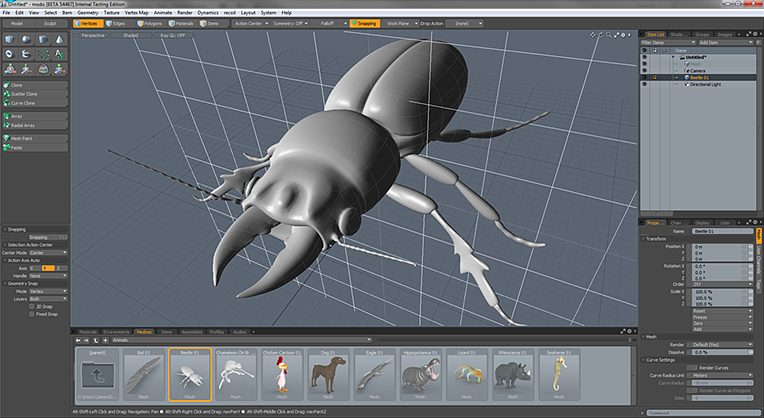
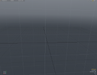
The Work Plane is a white grid that appears in the 3D openGL viewports. In this example above, the Work Plane has been highlighted for emphasis.
The Work Plane is an adaptive modeling aid that automatically adjusts itself to match the two major axes most closely aligned to your current screen axis, represented by a white grid within any of the 3D OpenGL viewports. When you rotate the Perspective viewport, the Work Plane snaps to one of the dominant planes, XY, XZ or XY. Action Centers often use the Work Plane position to determine the center and axis of tools when activated. When hauling, many tools also use the work plane to determine the axes of operation when this information cannot be derived from a specific tool handle.
While the default mode for the Work Plane is to automatically adjust to the screen's orientation, the work plane can also be locked and used as a construction plane. When applied as such, the Work Plane effectively positions the entire Modo universe to that fixed angle and position. There are a number of methods for manually setting the Work Plane to a specific center and axis. The work plane can be easily locked to a specific major axis and position, or you can snap the Work Plane to selected geometry or even just to the polygons directly under the mouse. This level of flexibility and control provides you with a fluid and rich set of options for editing your workspace.
Mastering the Work Plane allows you to do most, if not all, of your modeling in a single perspective viewport. That means more screen space remains for viewing the geometry and performing the various modeling tasks, allowing you to work more fluidly and accurately. Experiment with the Work Plane when using tools and hauling, so you can get a better grasp of its behaviors and use them to their advantage.
TIP: You can quickly offset the position of the Work Plane using a keyboard shortcut. Hover the mouse over some geometry in the scene where the Work Plane should move to, then press Alt+O. The Work Plane retains its orientation, but moves to the location where the mouse pointer intersects with the geometric element.
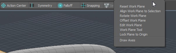
The Work Plane is a persistent function of the 3D Viewports, and is visible by default. You can toggle its display under the Visibility tab of the 3D Viewport Properties panel. To open it, hover the mouse over a viewport and press the O key. Additionally, you can toggle the Work Plane visibility by pressing the * (asterisk) key on the number pad. The controls for the Work Plane are located in the interface under the Work Plane menu button, or in the menu bar under Edit > Work Plane. You can also use the Home key to dynamically position the Work Plane to any geometry directly under the mouse pointer, centering under where the pointer tip intersects the polygon's surface and aligning it to the polygon's normal direction.
This command returns the Work Plane to it's default behavior. Only applies if the Work Plane has been aligned as a fixed construction plane.
Aligns the Work Plane to the current component selection as described below. If nothing is selected, the Work Plane gets aligned to the average normal of all foreground polygons.
When selecting vertices:
• If a single vertex is selected, only the center of the Work Plane is changed.
• If two vertices are selected, the first vertex sets the center and the workplane is altered to align the Z axis with the second vertex.
• If three vertices are selected, it uses the first vertex to set the center, the second to set the Z axis and the third defines the XZ plane.
• If more than three vertices are selected, the center is located at the average of their positions, and the plane is angled to put all vertices as close as possible to the XZ plane.
When selecting edges:
• If a single edge is selected, it is treated the same way as two vertices using the ends of the edge (above).
• If two edges are selected, they are treated the same as three vertices (above).
• If three or more edges are selected. this results in the same solution as vertices, using the end points of the edges as the vertices
When selecting polygons:
• If a single polygon is selected, the workplane is centered on that polygon with the Y axis aligned to the polygon normal. The longest edge of the polygon is along the Z axis.
• If multiple polygons are selected, the average normal is along the Y axis, and the system uses a best guess to determine correct orientation.
The Rotate Work Plane function provides you with a means to accurately rotate the Work Plane a defined number of degrees away from its current position. Invoking the command opens this dialog.
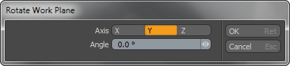
Axis: This option defines around which axis the Work Plane rotates, originating at the Work Plane origin (0,0,0) position.
Angle: Defines the number of degrees to rotate the Work Plane away from its home position.
The Offset Work Plane function provides you with a means to accurately position the Work Plane by way of an offset from its current position. Invoking the command opens this dialog.
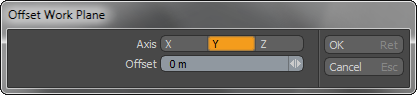
Axis: This option defines around which axis the Work Plane offset its position along.
Offset: Defines the distance to offset the Work Plan away from its current position.
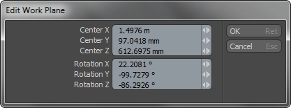
Displays the current values of the work plane as offset from the true World Origin position at 0,0,0. You can edit the values to precisely position and rotate the Work Plane.
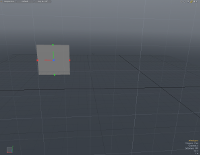
The Work Plane Tool allows for interactive placement of the Work Plane itself. When combined with Snapping, the Work Plane can be placed very accurately. The tool is found in the main Work Plane dropdown menu, selecting it activates the tool. Click in the 3D Viewport to draw the tools handles that allow for interactive placement. The initial click places the handles at the intersection of the mouse click position and the existing Work Plane. You see the standard 3-point axes handles colored accordingly, with a small square at the center and two more at the ends of the axes pointers. The initial square at the center defines the work plane's center and the other two work together with the center to define a plane.
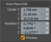
To use it, activate the tool, and then ensure that the Preview option is enabled in the tool's properties panel. Then click in the 3D Viewport, use the resulting tool handles to place the center and define the plane by clicking and dragging them in to the proper position. Numeric values on the tool properties panel can also be modifies to adjust the plane manually. Disabling the Preview option with the tool still active then places the Work Plane, locking it to the defined location. Press Q to drop the tool, allowing further editing of the scene with the newly defined Work Plane.
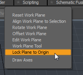
The Lock Plane to Origin toggle forces the Work Plane to intersect the World Origin position at 0,0,0. The Work Plane still aligns to the facing plane, and it may appear that it has shifted away from the origin. However, when you draw an object, it aligns to the Work Plane at zero distance from the World Origin along the axis that is perpendicular to the Work Plane.
For example, if the Work Plane appears to be aligned to the XY plane and you draw a primitive, the X,Y coordinates are determined as normal, by mouse position. However, the primitive origin is placed at Z=0. In this case, the Z-axis is perpendicular to the Work Plane, and the Work Plane is positioned at Z=0 to intersect the World Origin. The images below illustrate this process.
|
|
|
||
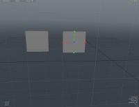
| 1. The Work Plane is aligned to the XY plane, a short distance behind Z=0. | 2. A flat cube primitive is drawn. (Lock Plane to Origin is off.) | 3. Lock Plane to Origin is activated. | ||
|
|
|||
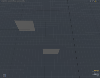
| 4. A second flat cube primitive is drawn. | 5. Looking overhead, notice that the second primitive is located at Z=0. |
TIP: To help draw primitives on the ground (XZ) plane, toggle Lock Plane to Origin on, and rotate the viewport so that the Work Plane aligns to the ground plane. If the primitive has a flat base, such as a cube or cylinder, draw the flat object and then extrude the height. This will locate the object on the ground plane. For objects that are initially drawn in 3D, or objects with a rounded base, you will need to adjust the Y-position to sit the object on the ground plane.
This toggle enables and disables the drawing of an axes handle widget in the viewport at the origin position of the Work Plane, making it easier to recognize the center and axis directions.