Camera Matching adjusts a camera viewpoint so that the perspective in a background image matches the perspective of the Modo 3D world. This allows you to place 3D objects as if they were part of the background image.
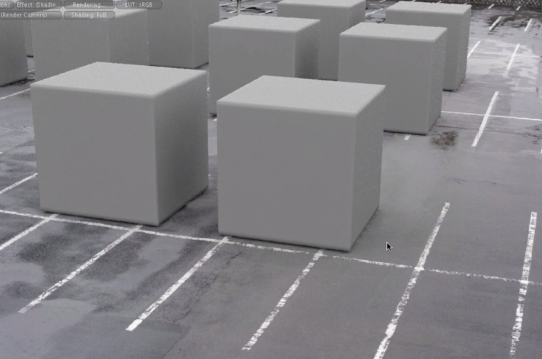
The images below demonstrate Camera Matching in action. This is a rendered output of a series of Modo cubes overlaid onto the image of a parking lot. The perspective of the cubes and the parking lot were matched using the Camera Matcher.
NOTE: The background image is loaded onto the camera. This is different to a Backdrop Item, which creates a new background plane in the Item List, and can be seen from any camera. To view a camera background image, you have to switch to the camera's view.
To match the camera background image to the 3D world, Modo needs to know the following:
| 1. | Where are the lines of perspective in the image? |
| 2. | Which axis is each line parallel to? |
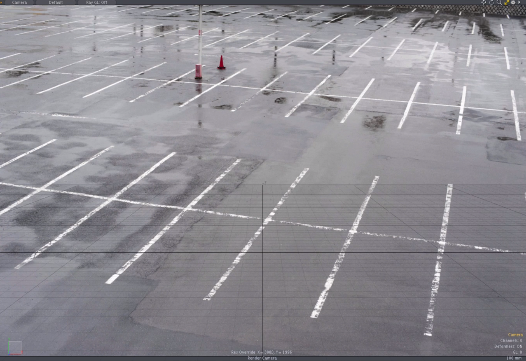
To provide Modo with this information, you must identify two pairs of perspective lines in the image, where each pair is parallel to one of the world axes. You then draw over these lines using the Camera Matcher. For example, in the image above, the markings that run from left to right provide good lines to match to the X-axis. The lines perpendicular to these, whose vanishing point is in the far distance, provide a good match to the Z-axis.
NOTE: One pair of lines must be orthogonal to the other pair.
The image below shows the basic steps for camera matching.
|
|
|
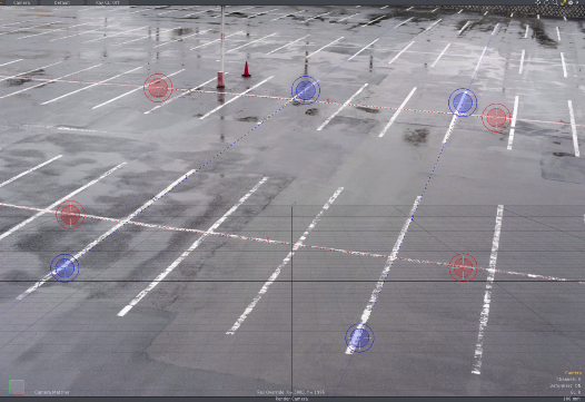
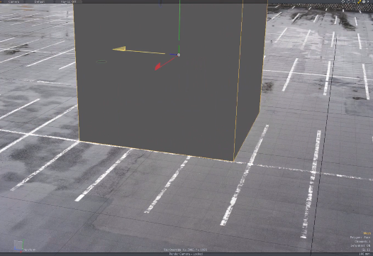
| Load the background image onto the camera. | Draw the perspective lines, and match the camera to the perspective. | Add models as required. Notice how the perspective of the model and the image now match. |
The Camera Matcher positions the camera at the World Origin with an orientation to match the perspective in the background image. For additional accuracy, you can draw a fifth line that describes the length of an object in the image. This adjusts the camera position so that the scale of the image matches the scale of the Modo world.
Once matched, you can view existing geometry against the background by either moving the geometry in-front of the camera, or translating the camera. Also, to help you draw new objects in front of the camera, the Camera Matcher lets you reposition the Work Plane relative to the camera.
Camera matching is performed in Setup mode using the Background Image properties tab in the camera's Item Properties panel.
NOTE: Each camera can have a single background image and camera matching configuration.
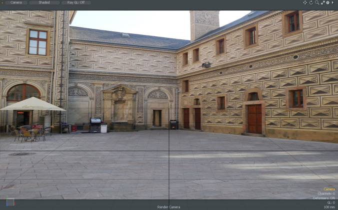
The Camera Matcher relies on two-point perspective, where orthogonal lines in the image converge at two vanishing points. The image below illustrates two-point perspective in a photograph of a building.
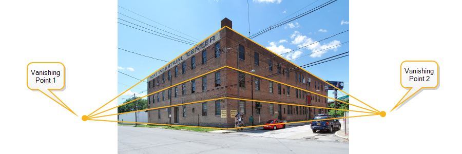
In this image, there are two orthogonal sets of lines; the lines on the left of the building corner are orthogonal to the lines on the right. Each set converges at a different vanishing point. Two-point perspective allows Modo to calculate a camera position with a high degree of accuracy.
NOTE: The lines used for a single axis must not run exactly parallel as they do not converge at a vanishing point.
The operations in this section are performed whilst looking from the selected camera's viewpoint. Follow these steps to select the camera and look through it.
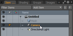
| 1. | Click on the camera in the Item List. |
| 2. | Select the Setup layout. |
TIP: In the Setup layout in Items mode, you can select a camera by clicking on it.
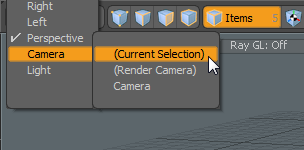
| 3. | Switch to the camera viewpoint by selecting Camera > (Current Selection) in the view selector in the top-left of the viewport. |
Camera matching requires a background image to match against. You can load the image into the camera using the Background Image properties.
| 1. | In the Background Image section of the camera's Item Properties, click on the Background Image control to open the image thumbnails. |
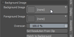
| 2. | Click the Add Clip dropdown and select (load image). |
This opens the image file browser.
| 3. | Browse to and select the background image. Click OK. |
The image appears in the background.
If the background image has a different aspect ratio to the render resolution, the image aspect ratio is automatically adjusted to fit the render resolution. Usually, this is not wanted as the camera background image adopts a different resolution to the original source image. To override this, you can adjust the render resolution to fit the background image, avoiding any distortion of the background image. This is done using the Resolution Override properties.
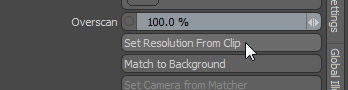
To ensure the render viewport is sized to the image, you can use the Set Resolution from Clip button.
| 1. | Select the Camera View tab in the camera Item Properties. |
| 2. | In the Background Image properties, click Set Resolution from Clip to set the render resolution to be the same as the background image. |
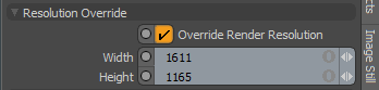
This activates Override Render Resolution in the Resolution Override properties. The Width and Height values have been changed to match the image resolution.
NOTE: Set Resolution from Clip also adjusts the aspect ratio of the film back for the camera, to ensure proper camera matching.
If you prefer not to use the source image resolution, you can resize the background image manually and use the new settings for the render resolution.
| 1. | Check Override Render Resolution in the Resolution Override properties. |
| 2. | Edit the Width and Height values to resize the image. |
NOTE: The Width and Height are adjusted independently unless you gang edit.
You can switch the image to a different color space if required.
| 1. | In the camera Item Properties, select the Image Still tab. |
| 2. | In the Color section, select the Colorspace. |
You match the camera to the image perspective by drawing four lines. These lines must meet the following criteria:
• Each line must run parallel to one of the world axes.
• Each line must be clear enough to draw over.
• Two lines should run in parallel to one axis, and two lines should run parallel to an orthogonal axis.
In the building image (see Adding a Background Image), you can see lines along the walls, at the roof, and along the floor. The back wall is orthogonal to the side wall, and they are a good match for the X and Z axes respectively. Each wall has a choice of lines that we can use for the matcher.
NOTE: You only need to match against two axes for the Camera Matcher to work. Choose which axes to use in the Camera Matcher properties.
| 1. | Ensure you're in the Setup layout with the camera selected, and the viewport looking through the camera. |
| 2. | Select the Camera View tab on the camera's Item Properties panel. |
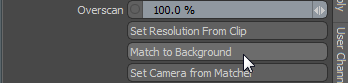
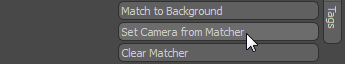
| 3. | In the Background Image properties, click the Match to Background button. |
| 4. | Click on the Tool Properties tab on the left of the Modo window. |
This opens the Camera Matcher properties.
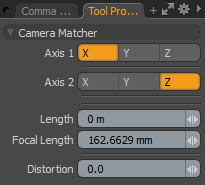
| 5. | Choose the two axes to match against by selecting values for Axis 1 and Axis 2. For example, in the image of the building above, the X and Z axes are a good choice as they both have clear matching lines. |
The first two lines you draw are matched against Axis 1.
NOTE: The choice of axes is guided by the content of the image. If you have clear perspective lines such as building edges or road markings, use these and match them to the world axes. Features that cross the image from left to right, match the X-axis. Road markings that extend to the far horizon are a good match for the Z-axis, as would building edges that are perpendicular to those being used for the X-axis. The sides of buildings, poles, or towers that extend upwards would match the Y-axis.
| 6. | Click and drag on the image to draw the first line. Once drawn, you can click and drag the end-points to adjust the line. |
| 7. | To make fine adjustments to the line end-point, right-click and drag the end-point. |
Right-clicking on the end-point magnifies a portion of the image around the end-point.
The cross in the center of the magnified region marks the center of the end-point.
NOTE: The line is color coded to match the axis color.
| 8. | Once the first line is correctly aligned, click and drag to draw the second line for Axis 1. You can then make adjustments as needed. |
| 9. | Click and drag to draw the first line for Axis 2. Notice that the color of the line differs. |
| 10. | Adjust the line to match the image. |
| 11. | Click and drag to draw the second line for Axis 2. Adjust as required. |
| 12. | With four lines drawn, you can make adjustments to each one until you have a good alignment. |
NOTE: At this stage, for a more accurate camera position, you can also add the length line. This is explained in Matching the Scale
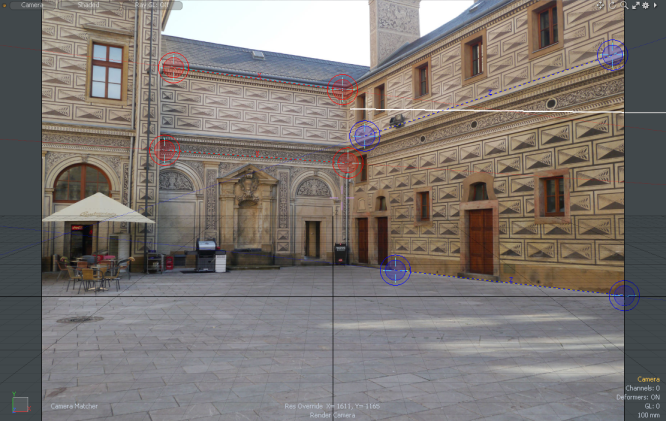
| 13. | Click Set Camera from Matcher to match the camera to the Modo world. |
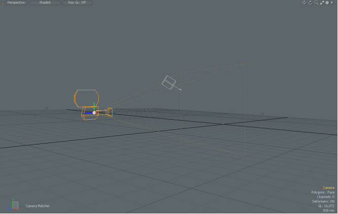
The perspective lines disappear and the camera is re-oriented at the origin. The image below shows the new camera position as seen in the Perspective view.
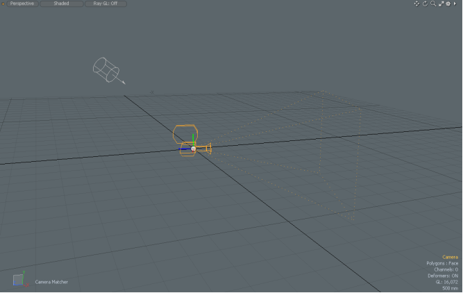
Modo objects visible from the camera now match the perspective of the background image. You can place objects as required, for more information see Viewing Objects from the Camera.
TIP: If there are objects in the world but they are not visible from the camera, switch to Perspective view and place the objects in front of the camera. Once visible from the camera, the objects can be manipulated in the Camera view.
You can also translate the camera without adjusting its orientation to face any objects in the scene. To translate the camera it must be unlocked.
NOTE: The camera matcher stays live, which means that any lines drawn can be edited when you click Match to Background, or when you click in the viewport when the tool is active.
The camera matcher lets you draw a fifth line to adjust the camera location. The new camera location enables the scale in the background image to match the scale of the 3D world. This allows you to size and place objects more accurately to match the background image.
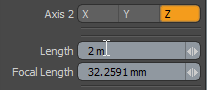
In addition to drawing the line, you need to enter the length that the line measures in the background image. For example, if there's a 2 m doorway in the image, you would draw a line along the full height of the doorway and enter 2 m for the line's length.
NOTE: To draw a length line, you must have drawn the four perspective lines.
| 1. | If you've just drawn the four perspective lines and camera matcher is active, skip to step 3. |
| 2. | With the viewport on the camera, click Match to Background in the Background Image properties. |
| 3. | Click and drag to draw the length line. |
The length line is drawn dotted white and black.
NOTE: The end of the line with the dotted circle indicates the World Origin point. The matcher finds a position for the camera relative to this point.
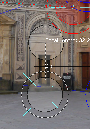
NOTE: As a reminder, the current focal length of the camera is shown at the end of the line.
| 4. | Adjust the line as you would with the perspective lines. Right-click+drag an end-point to magnify. |
| 5. | Open the Tool Properties panel on the left and enter the Length in meters. |
| 6. | Click Set Camera from Matcher to match the scale. |
The lines disappear and the camera is repositioned. You can swap into Perspective view to check the camera position.
NOTE: Moving the camera may mean that objects are no longer in view. If this happens, swap into Perspective view to move the objects back in-front of the camera.
To place existing geometry in front of the camera, you can either move the geometry or translate the camera. Make sure that you don't rotate the camera as this will lose the perspective match. The Camera Matcher automatically locks the camera, so you need to unlock it before moving it. A locked camera is indicated by a small padlock icon as shown below.
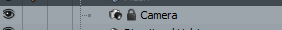
To unlock the camera, right-click on the camera item and select Lock/Unlock.
New geometry will be drawn on the Work Plane as normal. To draw geometry in the camera view you can set the Work Plane relative to the camera as explained in the following section.
To help you place objects against the background image, you can set the axes of the Work Plane to match the axes that are drawn when camera matching. This adjusts the Work Plane orientation relative to the current camera. If you have added a length line, the Work Plane is also moved to the location of the length line.
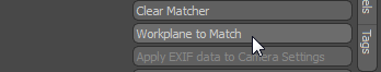
Match the Work Plane by clicking Set Camera from Matcher in the Background Image properties of the camera's Item Properties.
NOTE: Without a length line, the Work Plane is positioned at the World Origin.
Modo's Camera Matcher includes a Lens Distortion Estimator to compensate for real-world lens distortion. Lens distortion is a common phenomena in optics, where a straight line in the real-world may appear slightly curved in a photo due to lens design. Lens distortion is most apparent in zoomed or wide-angle shots, and is easily seen at extreme focal lengths such as those in fisheye lenses.
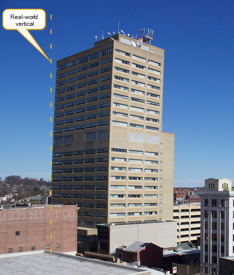
The image below shows subtle lens distortion along the vertical edge of a building. Notice how the edge of the building curves away from the vertical axis.
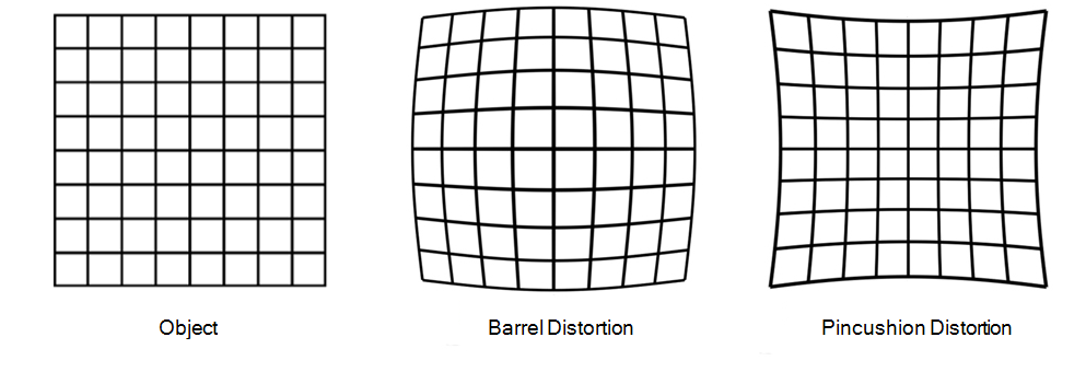
Two common types of lens distortion seen in photography are barrel distortion and pincushion distortion. Barrel distortion typically occurs at wide angles, and the lines curve outwards from the center of the image. Pincushion distortion occurs in zoomed images, and the lines curve inwards. The image below illustrates the two effects.
You can see in the image of the building above, the distorted edge of the building is convex, and therefore due to barrel distortion.
Modo's Lens Distortion Estimator ensures that the edges of objects in the 3D world are curved to match the edges in the image, where the curvature is due to lens distortion. The Estimator is able to solve for subtle lens distortion such as the type shown in the image above. It is less likely to work with extreme lens distortion as seen in fisheye lenses.
NOTE: You only see the effects of the Lens Distortion Estimator in the rendered output.
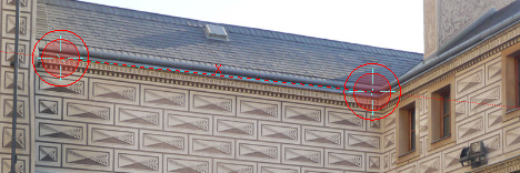
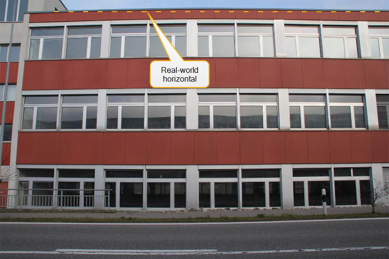
You can see lens distortion in the image below. Notice how the horizontal building lines are subject to barrel distortion. This is particularly visible across the roof-edge of the building.
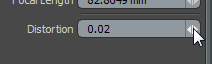
Lens distortion is applied to rendered objects by adjusting the Distortion parameter on the Tool Properties panel. Distortion can take positive or negative values:
• Positive values are used to adjust for barrel distortion.
• Negative values compensate for pincushion distortion.
NOTE: Add lens distortion after you have drawn the perspective lines.
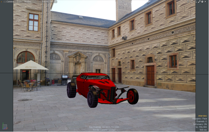
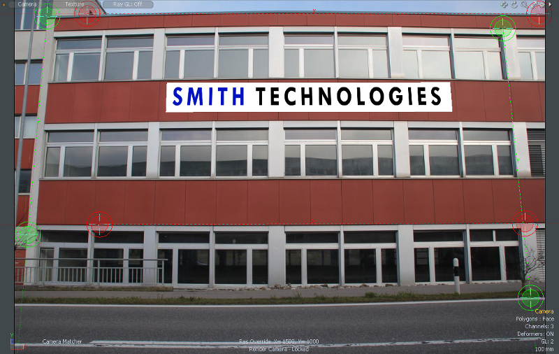
| 1. | Position objects against the background as required. The image below shows a textured polygon that has been added to a building facade using Modo. |
Observe how the building in the image is subject to lens distortion but the Modo geometry is not.
| 2. | If the Camera Matcher is active, skip to step 4. |
| 3. | In Setup mode, with the camera selected and the viewport looking from the camera, click Match to Background. |
| 4. | In the Tool Properties panel, increase or decrease the Distortion value for barrel or pincushion distortion respectively. |
A non-zero Distortion value reveals the lens distortion reference grids in the camera viewport. The green grid shows undistorted lines as a base reference. The orange grid shows the degree of lens distortion according to the Distortion value.
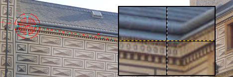
| 5. | As you adjust the value, look closely at the perspective lines. You can see that a green line is drawn between the end-points to show the effect of barrel distortion. The image below shows a green distortion line originating from the perspective line that was drawn along the roof-edge of the building. |
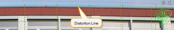
| 6. | Match the green line to the line in the image and click Set Camera from Matcher to apply the distortion. |
TIP: You can also use the orange grid to estimate the level of distortion required.
| 7. | When you're happy with the Distortion value, click Set Camera to Matcher. |
| 8. | Press F9 to render the output and check the results. |
NOTE: To render from the camera's point-of-view, the camera must be the Render Camera. This is set in the Render Item's properties.

| 9. | If you need to make further adjustments, return to step 2. |
If you want to reset the Camera Matcher and start again, click Clear Matcher in the Background Image properties of the camera's Item Properties.
![]()