The Illuminate node is used to sample the light that falls onto a given surface. For each sample, the result is either illuminated or in shadow. The sample results can be derived from specific light sources, or be a combination of all lights in the scene. This can be used, for example, to mask surface attributes to appear only in areas of illumination or shadow, or to use the illumination amount to drive a specific channel, for example, using it to scale the scale/size channel of a procedural texture.
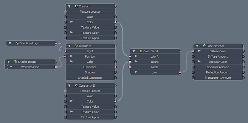
The Illuminate node is added to the Schematic Viewport using the Add function, found in the pop-up menu under Shader Inputs > Illuminate. With the node selected in the Schematic viewport, you can define the Mode, controlling if all lights in a scene are used to evaluate illumination, or if only the lights connected to the nodes Light input are evaluated. When working with connected lights the relationship output connector from the light is connected to the Light input on the node, you can connect any number of lights. Once connected, the results of the illumination are evaluated per sample and the value returned to its specific output.
NOTE: For information on working with node graphs, see Schematic Viewport
Illuminate Node Example:
Illuminate Position Example:
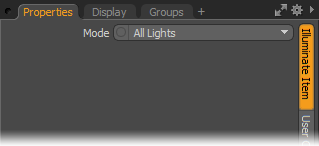
The following Illuminate Item options are available for the Illuminate node:
• Mode - The Mode option determines sampling based on using specific lights in the scene with the Connected Lights option or using All Lights in the scene.
Schematic Node: Illuminate
|
Option |
Description |
|---|---|
|
Light Input |
When the Illuminate items Mode option is set to Connected Light only the Light items specifically connected to the input are sampled as part of the node evaluation. |
|
Position Input |
The Position input defines the location of the sampling target. By default this is the World Position, a shader input is connected automatically, see Shader Inputs. The World Position setting means that the illumination sampling of the node takes place in the same location where the initial shading sample is derived. You can disconnect the Shader Input and connect a specific XYZ location if you want to sample the illumination of a specific point (like a light detector), or use any of the numerous vector math nodes to warp the sampling locations, to produce interesting results. |
|
Color Output |
Outputs the color of the connected light on a per sample basis. |
|
Luminance Output |
The output value represents where the illumination of the lights is present on the surface. |
|
Shadow Output |
The output value represents where the illumination of the lights is hidden in shadow on the surface. |
|
Shaded Luminance Output |
The output value represents the Diffuse amount (reflected light) from the illuminated surface. |