The particle audio modifier uses the frequency response of an imported audio file to modify any (or all) of the three basic item transforms (Move, Scale and Rotate) when assigned to a particle source. This provides a means to animate the final elements in unique and interesting ways, that synchronize to the music. The way it works is by dividing the audio spectrum into the same number of samples as the number of particles. At each designated sample location the amount of audio variance is converted to a percentage and applied to the desired transform channel.
You can add a particle audio modifier item by using the Add Item function of the Items List. Click the button to open the menu, then select the Particles > Modifiers > Particle Audio Modifier option.
Next you need to connect the modifier to a point source and specify the audio file. This is best accomplished in the Schematic viewport.
Once added, you need to specify the point source that you wish to affect. Once the originating point source is defined, you also need to specify the particle modifier item as the source in the final item. If thought of like a chain, the originating particle generation is defined as the source in the modifier, and then the modified values are fed into the final effect, such as a Replicator, Blob, Volume or Sprite. The source must be defined in this order so as to produce the intended result.
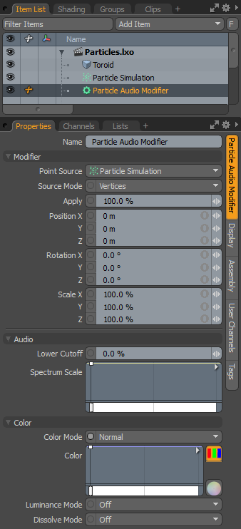
When applying the audio modifier to an active particle simulation, you need to connect the modifier in the proper order within the Schematic viewport. For existing networks, simply select the connector between the simulation item and the target and add the modifier. The audio modifier is found in the Schematic view in the Add... menu under Particles > Modifiers > Particle Audio Modifier. When selected, the following attributes are available in the Properties panel.
|
Option |
Description |
|---|---|
|
Name |
Displays the current item name. To change it, click on the field and type in the new name. |
|
Modifier |
|
|
Point Source |
Defines the source of the particles that are affected by the modifier. |
|
Source Mode |
Specifies the way the particle modifier affects the source. Vertices uses the point positions, Polygons uses the polygon centers, and Detached Vertices uses the point positions of vertices that are not part of polygons. |
|
Apply |
Acts as a multiplier, controlling the overall strength of the transforms applied to the source particles. |
|
PositionX/Y/Z |
Determines a position value for each individual axis as an offset from the particle's originating position. |
|
RotationX/Y/Z |
Determines a rotation value for each individual axis as an offset from the particle's originating orientation. |
|
Scale X/Y/Z |
Determines a scaling value for each individual axis as an increase/decrease from the particle's initial size. |
|
Audio |
|
|
Lower Cutoff |
Defines a minimum threshold in the frequency range where anything below the defined threshold is ignored. This is useful to eliminate some slight motion that might appear in a noisy audio file. |
|
Spectrum Scale |
A multiplier that determines the influence of a given frequency. Lower frequencies are on the left of the gradient and higher ones to the right. This can also be used as a virtual crossover to completely cut out certain frequency ranges, for example, the audio is driving a woofer animation, and a key can be added to cut out all of the high end frequencies. |
|
Color |
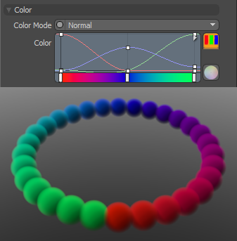
Allows you to use mini gradient editors to assign and control different attributes for the resulting particles. These attributes are then passed along to the final effect, working with both volumes and sprites. The gradient values are generated sequentially, dividing the gradient itself into the number of generated particles it is assigned to, each receiving the value for that position along the gradient. For example, a red to blue gradient assigned to a linear array of particles produces one red particle at the start. The particle colors then fade toward the blue color in even increments along the length of the array. There are three different settings that can be applied to their associated surface attributes. Any of these functions are enabled by selecting any option other than Off (the default value that disabled the function). The selected Mode determines the blending of the gradient with the base setting of the target element. |
|
Color Mode |
Determines how the resulting gradient applies, defining the blending mode of the colors as they apply to the base particle coloring. The Color gradient editor that opens allows you to define the actual gradient values that are applied. |
|
Luminance Mode |
Determines how the resulting gradient applies, defining the blending mode of the luminosity value as it applies to the base particle luminosity. The Luminosity gradient editor that opens allows you to define the actual gradient values that are applied. |
|
Dissolve Mode |
Determines how the resulting gradient applies, defining the blending mode of the colors as they apply to the base particle transparency. The Dissolve gradient editor that opens allows you to define the actual gradient values that are determine the transparent amount.
A Normal color mode gradient applied to a particle generator's radial array |