The random particle modifier randomly applies any or all of the three basic transforms (Move, Scale and Rotate) to a procedurally generated particle source. The random particle modifier is applied as the go-between for any item's point source, providing and easy way to add natural variations to the resulting particles. Interesting effects can also be created when combined with falloffs and particle operators.
You can add a random particle modifier item by using the Add Item function of the Items List. Click the button to open the menu, then select the Particles > Modifiers > Particle Random Modifier option.
Once added, you need to specify the point source that you wish to affect. Once the originating point source is defined, you also need to specify the particle random modifier item as the source in the final item. If thought of like a chain, the originating particle generation is defined as the source in the modifier, and then the modified values are fed into the final effect, such as a Replicator, Blob, Volume or Sprite. The source must be defined in this order so as to produce the intended result.
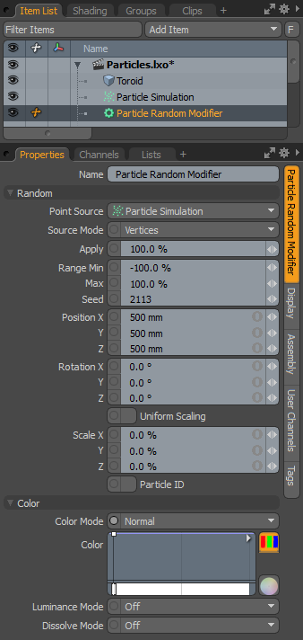
When applying the random modifier to an active particle simulation, you need to connect the modifier in the proper order within the Schematic viewport. For existing networks, simply select the connector between the simulation item and the target and add the modifier. The random modifier is found in the Schematic view in the Add... menu under Particles > Modifiers > Particle Random Modifier. When selected, the following attributes are available in the Properties panel.
|
Option |
Description |
|---|---|
|
Name |
Displays the current item name. To change it, click on the field and type in the new name. |
|
Random |
|
|
Point Source |
Defines the source of the particles that are affected by the modifier. |
|
Source Mode |
Specifies the way the particle modifier affects the source. Vertices uses the point positions, Polygons uses the polygon centers, and Detached Vertices uses the point positions of vertices that are not part of polygons. |
|
Apply |
Determines the overall degree that the expression affects the target. At 0% the target is not affected at all, at 100% the target is fully affected. This allows you to transition to the modified state. |
|
Range Min/Max |
Determines the amount of transform applied to the target over the entire range of the particles acting as a multiplier on the value. For example, if the Scale is set to 200% on all three axes, and the Range Min/Max is -100%/100% respectively, then the first particle would be scaled 200%, attenuating the value toward the last particle scaled at 200%. The range is determined in the order of the Particle ID. |
|
Seed |
The initial number used when generating the random procedural values. Different Seed values produce different random variations and can be useful in changing the result. |
|
PositionX/Y/Z |
Defines the position values added to the target for each axes. |
|
RotationX/Y/Z |
Defines the rotation values added to the target for each axes. |
|
Uniform Scaling |
When enabled, the random scaling factor is applied evenly on all axes. |
|
Scale X/Y/Z |
Defines the scale values added to the target for each axes. |
|
Particle ID |
When enabled, the unique ID identifier values are randomized, instead of sequential of the initial particle. |
|
Color |
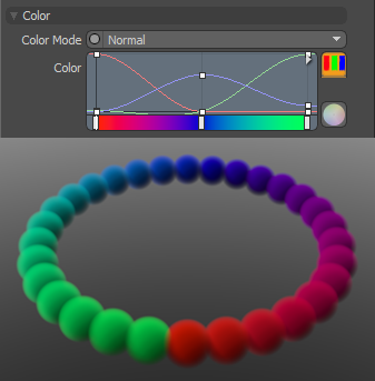
Allows you to use mini gradient editors to assign and control different attributes for the resulting particles. These attributes are then passed along to the final effect, working with both volumes and sprites. The gradient values are generated sequentially, dividing the gradient itself into the number of generated particles it is assigned to, each receiving the value for that position along the gradient. For example, a red to blue gradient assigned to a linear array of particles produces one red particle at the start. The particle colors then fade toward the blue color in even increments along the length of the array. There are three different settings that can be applied to their associated surface attributes. Any of these functions are enabled by selecting any option other than Off (the default value that disabled the function). The selected Mode determines the blending of the gradient with the base setting of the target element. |
|
Color Mode |
Determines how the resulting gradient applies, defining the blending mode of the colors as they apply to the base particle coloring. The Color gradient editor that opens allows you to define the actual gradient values that are applied. |
|
Luminance Mode |
Determines how the resulting gradient applies, defining the blending mode of the luminosity value as it applies to the base particle luminosity. The Luminosity gradient editor that opens allows you to define the actual gradient values that are applied. |
|
Dissolve Mode |
Determines how the resulting gradient applies, defining the blending mode of the colors as they apply to the base particle transparency. The Dissolve gradient editor that opens allows you to define the actual gradient values that are determine the transparent amount.
A Normal color mode gradient applied to a particle generator's radial array |